- Steps of clarification
- Inorganic coagulants
- Polyelectrolytes
- Color Reduction
- Conventional clarification equipment
- In-line clarification
Suspended matter in raw water supplies is removed by various methods to provide a water suitable for domestic purposes and most industrial requirements. The suspended matter can consist of large solids, settable by gravity alone without any external aids, and nonsettleable material, often colloidal in nature. Removal is generally accomplished by coagulation, flocculation, and sedimentation. The combination of these three processes is referred to as conventional clarification.
Coagulation is the process of destabilization by charge neutralization. Once neutralized, particles no longer repel each other and can be brought together. Coagulation is necessary for the removal of the colloidal-sized suspended matter.
Flocculation is the process of bringing together the destabilized, or "coagulated," particles to form a larger agglomeration, or "floc."
Sedimentation refers to the physical removal from suspension, or settling, that occurs once the particles have been coagulated and flocculated. Sedimentation or subsidence alone, without prior coagulation, results in the removal of only relatively coarse suspended solids.
Finely divided particles suspended in surface water repel each other because most of the surfaces are negatively charged. The following steps in clarification are necessary for particle agglomeration:
-
Coagulation. Coagulation can be accomplished through the addition of inorganic salts of aluminum or iron. These inorganic salts neutralize the charge on the particles causing raw water turbidity, and also hydrolyze to form insoluble precipitates, which entrap particles. Coagulation can also be effected by the addition of water-soluble organic polymers with numerous ionized sites for particle charge neutralization.
- Flocculation. Flocculation, the agglomeration of destabilized particles into large particles, can be enhanced by the addition of high-molecular-weight, water-soluble organic polymers. These polymers increase floc size by charged site binding and by molecular bridging.
Therefore, coagulation involves neutralizing charged particles to destabilize suspended solids. In most clarification processes, a flocculation step then follows. Flocculation starts when neutralized or entrapped particles begin to collide and fuse to form larger particles. This process can occur naturally or can be enhanced by the addition of polymeric flocculant aids.
Table 5-1 lists a number of common inorganic coagulants. Typical iron and aluminum coagulants are acid salts that lower the pH of the treated water by hydrolysis. Depending on initial raw water alkalinity and pH, an alkali such as lime or caustic must be added to counteract the pH depression of the primary coagulant. Iron and aluminum hydrolysis products play a significant role in the coagulation process, especially in cases where low-turbidity influent waters benefit from the presence of additional collision surface areas.
Table 5-1. Common inorganic coagulants
| Name | Typical Formula | Typical Strength | Typical Forms Used in Water Treatment | Density | Typical Uses |
| Aluminum sulfate | Al2(SO4)3· 14 to 18 H2O |
17% Al2O3 | lump, granular, or powder | 60-70 lb/ft3 | primary coagulant |
| Alum | 8.25% Al2O3 | liquid | 11.1 lb/gal | ||
| Aluminum chloride | AlCl3·6H2O | 35% AlCl3 | liquid | 12.5 lb/gal | primary coagulant |
| Ferric sulfate | Fe2(SO4)3·9H2O | 68% Fe2(SO4)3 | granular | 70-72 lb/ft3 | primary coagulant |
| Ferric-floc | Fe2(SO4)3·9H2O | 41% Fe2(SO4)3 | solution | 12.3 lb/gal | primary coagulant |
| Ferric chloride | FeCl3 | 60% FeCl3, 35-45% FeCl3 |
crystal, solution | 60-64 lb/ft3 11.2-12.4 lb/gal |
primary coagulant |
| Sodium aluminate | Na2Al2O4 | 38-46% Na2Al2O4 | liquid | 12.3-12.9 lb/gal | primary coagulant; cold/hot precipitation softening |
Variation in pH affects particle surface charge and floc precipitation during coagulation. Iron and aluminum hydroxide flocs are best precipitated at pH levels that minimize the coagulant solubility. However, the best clarification performance may not always coincide with the optimum pH for hydroxide floc formation. Also, the iron and aluminum hydroxide flocs increase volume requirements for the disposal of settled sludge.
With aluminum sulfate, optimum coagulation efficiency and minimum floc solubility normally occur at pH 6.0 to 7.0. Iron coagulants can be used successfully over the much broader pH range of 5.0 to 11.0. If ferrous compounds are used, oxidation to ferric iron is needed for complete precipitation. This may require either chlorine addition or pH adjustment. The chemical reactions between the water's alkalinity (natural or supplemented) and aluminum or iron result in the formation of the hydroxide coagulant as in the following:
| Al2(SO4)3 | + | 6NaHCO3 | = | 2Al(OH)3- | + | 3Na2SO4 | + | 6CO2 |
| aluminum sulfate | sodium bicarbonate | aluminum hydroxide | sodium sulfate | carbon dioxide |
| Fe2(SO4)3 | + | 6NaHCO3 | = | 2Fe(OH)3- | + | 3Na2SO4 | + | 6CO2 |
| ferric sulfate | sodium bicarbonate | ferric hydroxide | sodium sulfate | carbon dioxide |
| Na2Al2O4 | + | 4H2O | = | 2Al(OH)3- | + | 2NaOH |
| sodium aluminate | water | aluminum hydroxide | sodium hydroxide |
The term polyelectrolytes refers to all water-soluble organic polymers used for clarification, whether they function as coagulants or flocculants.
Water-soluble polymers may be classified as follows:
- anionic-ionize in water solution to form negatively charged sites along the polymer chain
- cationic-ionize in water solution to form positively charged sites along the polymer chain
- nonionic-ionize in water solution to form very slight negatively charged sites along the polymer chain
Polymeric primary coagulants are cationic materials with relatively low molecular weights (under 500,000). The cationic charge density (available positively charged sites) is very high. Polymeric flocculants or coagulant aids may be anionic, cationic, or nonionic. Their molecular weights may be as high as 50,000,000. Table 5-2 describes some typical organic polyelectrolytes.
For any given particle there is an ideal molecular weight and an ideal charge density for optimum coagulation. There is also an optimum charge density and molecular weight for the most efficient flocculant.
Because suspensions are normally nonuniform, specific testing is necessary to find the coagulants and flocculants with the broadest range of performance.
Primary Coagulant Polyelectrolytes
The cationic polyelectrolytes commonly used as primary coagulants are polyamines and poly-(DADMACS). They exhibit strong cationic ionization and typically have molecular weights of less than 500,000. When used as primary coagulants, they adsorb on particle surfaces, reducing the repelling negative charges. These polymers may also bridge, to some extent, from one particle to another but are not particularly effective flocculants. The use of polyelectrolytes permits water clarification without the precipitation of additional hydroxide solids formed by inorganic coagulants. The pH of the treated water is unaffected.
The efficiency of primary coagulant poly-electrolytes depends greatly on the nature of the turbidity particles to be coagulated, the amount of turbidity present, and the mixing or reaction energies available during coagulation. With lower influent turbidities, more turbulence or mixing is required to achieve maximum charge neutralization.
Raw waters of less than 10 NTU (Nephelometric Turbidity Units) usually cannot be clarified with a cationic polymer alone. Best results are obtained by a combination of an inorganic salt and cationic polymer. In-line clarification should be considered for raw waters with low turbidities.
Generally, waters containing 10 to 60 NTU are most effectively treated with an inorganic coagulant and cationic polymer. In most cases, a significant portion of the inorganic coagulant demand can be met with the cationic polyelectrolyte. With turbidity greater than 60 NTU, a polymeric primary coagulant alone is normally sufficient.
In low-turbidity waters where it is desirable to avoid using an inorganic coagulant, artificial turbidity can be added to build floc. Bentonite clay is used to increase surface area for adsorption and entrapment of finely divided turbidity. A polymeric coagulant is then added to complete the coagulation process.
The use of organic polymers offers several advantages over the use of inorganic coagulants:
- The amount of sludge produced during clarification can be reduced by 50-90%. The approximate dry weight of solids removed per pound of dry alum and ferric sulfate are approximately 0.25 and 0.5 lb, respectively.
- The resulting sludge contains less chemically bound water and can be more easily dewatered.
- Polymeric coagulants do not affect pH. Therefore, the need for supplemental alkalinity, such as lime, caustic, or soda ash, is reduced or eliminated.
- Polymeric coagulants do not add to the total dissolved solids concentration. For example, 1 ppm of alum adds 0.45 ppm of sulfate ion (expressed as CaCO3). The reduction in sulfate can significantly extend the capacity of anion exchange systems.
- Soluble iron or aluminum carryover in the clarifier effluent may result from inorganic coagulant use. Therefore, elimination of the inorganic coagulant can minimize the deposition of these metals in filters, ion exchange units, and cooling systems.
Coagulant Aids (Flocculants)
In certain instances, an excess of primary coagulant (whether inorganic, polymeric, or a combination of both) may be fed to promote large floc size and to increase settling rate. However, in some waters, even high doses of primary coagulant will not produce the desired effluent clarity. A polymeric coagulant aid added after the primary coagulant may, by developing a larger floc at low treatment levels, reduce the amount of primary coagulant required.
Generally, very high-molecular-weight, anionic polyacrylamides are the most effective coagulant aids. Nonionic or cationic types have proven successful in some clarifier systems. Essentially, the polymer bridges the small floc particles and causes them to agglomerate rapidly into larger, more cohesive flocs that settle quickly. The higher-molecular-weight polymers bridge suspended solids most effectively.
Coagulant aids have proven quite successful in precipitation softening and clarification to achieve improved settling rates of precipitates and finished water clarity.
Frequently, the objective of clarification is the re-duction of color. Swamps and wetlands introduce color into surface waters, particularly after heavy rainfalls. Color-causing materials can cause various problems, such as objectionable taste, increased microbiological content, fouling of anion exchange resins, and interference with coagulation and stabilization of silt, soluble iron, and manganese.
Most organic color in surface waters is colloidal and negatively charged. Chemically, color-producing compounds are classified as humic and fulvic acids. Color can be removed by chlorination and coagulation with aluminum or iron salts or organic polyelectrolytes. Chlorine oxidizes color compounds, while the inorganic coagulants can physically remove many types of organic color by neutralization of surface charges. The use of chlorine to oxidize organic color bodies may be limited due to the production of chlorinated organic by-products, such as trihalomethanes. Additional color removal is achieved by chemical interaction with aluminum or iron hydrolysis products. Highly charged cationic organic polyelectrolytes can also be used to coagulate some types of color particles.
Coagulation for color reduction is normally carried out at pH 4.5 to 5.5. Optimum pH for turbidity removal is usually much higher than that for color reduction. The presence of sulfate ions can interfere with coagulation for color reduction, whereas calcium and magnesium ions can improve the process and broaden the pH range in which color may be reduced effectively.
Conventional Clarification Equipment
The coagulation/flocculation and sedimentation process requires three distinct unit processes:
- high shear, rapid mix for coagulation
- low shear, high retention time, moderate mixing for flocculation
- liquid and solids separation
Horizontal Flow Clarifiers
Originally, conventional clarification units consisted of large, rectangular, concrete basins divided into two or three sections. Each stage of the clarification process occurred in a single section of the basin. Water movement was horizontal with plug flow through these systems.
Because the design is suited to large-capacity basins, horizontal flow units are still used in some large industrial plants and for clarifying municipal water. The retention time is normally long (up to 4-6 hr), and is chiefly devoted to settling. Rapid mix is typically designed for 3-5 min and slow mix for 15-30 min. This design affords great flexibility in establishing proper chemical addition points. Also, such units are relatively insensitive to sudden changes in water throughput.
The long retention also allows sufficient reaction time to make necessary adjustments in chemical and polymer feed if raw water conditions suddenly change. However, for all but very large treated water demands, horizontal units require high construction costs and more land space per unit of water capacity.
Upflow Clarifiers
Compact and relatively economical, upflow clarifiers provide coagulation, flocculation, and sedimentation in a single (usually circular) steel or concrete tank. These clarifiers are termed "upflow" because the water flows up toward the effluent launders as the suspended solids settle. They are characterized by increased solids contact through internal sludge recirculation. This is a key feature in maintaining a high-clarity effluent and a major difference from horizontal clarifiers.
Because retention time in an upflow unit is approximately 1-2 hr, upflow basins can be much smaller in size than horizontal basins of equal throughput capacity. A rise rate of 0.70-1.25 gpm/ft² of surface area is normal for clarification. Combination softening-clarification units may operate at up to 1.5 gpm/ft² of surface area due to particle size and densities of precipitated hardness.
In order to achieve high throughput efficiency, upflow units are designed to maximize the linear overflow weir length while minimizing the opportunity for short-circuiting through the settling zone. In addition, the two mixing stages for coagulation and flocculation take place within the same clarification tank.
Although upflow units may provide more efficient sedimentation than horizontal designs, many upflow clarifiers compromise on the rapid and slow mix sequences. Some types provide rapid, mechanical mixing and rely on flow turbulence for flocculation; others eliminate the rapid mix stage and provide only moderate turbulence for flocculation. However, in most cases, users can overcome rapid mix deficiencies by adding the primary coagulant further upstream of the clarifier.Figure 5-1 shows the rapid mix, slow mix, and settling zones of a typical upflow, solids-contact clarifier.
Sludge Blanket and Solids-Contact Clarification
Most upflow designs are called either "sludge blanket" or "solids-contact" clarifiers. After coagulation and/or flocculation in the sludge blanket units, the incoming water passes through the suspended layer of previously formed floc. Figure 5-2 shows an upflow sludge blanket clarifier.
Because the centerwell in these units is often shaped like an inverted cone, the rise rate of the water decreases as it rises through the steadily enlarging cross section. When the rise rate decreases enough to equal the settling rate of the suspended floc exactly, a distinct sludge/liquid interface forms.
Sludge blanket efficiency depends on the filtering action as the freshly coagulated or flocculated water passes through the suspended floc. Higher sludge levels increase the filtration efficiency. In practice, the top sludge interface is carried at the highest safe level to prevent upsets that might result in large amounts of floc carryover into the overflow. Excessive sludge withdrawal or blowdown should also be avoided. The sludge blanket level is often highly sensitive to changes in throughput, coagulant addition, and changes in raw water chemistry and temperature.
"Solids-contact" refers to units in which large volumes of sludge are circulated internally. The term also describes the sludge blanket unit and simply means that prior to and during sedimentation the chemically treated water contacts previously coagulated solids. Solids-contact, slurry pool units do not rely on filtration as in sludge blanket designs.
Solids-contact units often combine clarification and precipitation softening. Bringing the incoming raw water into contact with recirculated sludge improves the efficiency of the softening reactions and increases the size and density of the floc particles. Figure 5-3 illustrates a typical solids-contact unit.
In-line clarification is the process of removing raw water turbidity through the addition of coagulant just prior to filtration. In-line clarification is generally limited to raw waters with typical turbidities of less than 20 NTU, although upflow filters may tolerate higher loading. Polyelectrolytes and/or inorganic coagulants are used to improve filtration efficiency and run length. Polymers are favored because they do not create additional suspended solids loading, which can shorten filter run length.
Filter design may be downflow or upflow, depending on raw water turbidity and particle size. The downflow dual-media unit generally consists of layers of various grades of anthracite and sand supported on a gravel bed. After backwashing, the larger anthracite particles separate to the top of the bed, while the more dense, smaller sand particles are at the bottom. The purpose is to allow bed penetration of the floc, which reduces the potential for excessive pressure drops due to blinding off the top portion of filter media. Thus, higher filtration rates are realized without a significant loss in effluent quality. Normal filtration rates are 5-6 gpm/ft².
Coagulant Selection and Feeding for In-Line Clarification
The choice of a polymer coagulant and feed rate depends on equipment design and influent water turbidity. Initially, in-line clarification was used in the treatment of low-turbidity waters, but it is now being used on many types of surface waters. For most waters, the use of a polymeric cationic coagulant alone is satisfactory. However, the addition of a high-molecular-weight, anionic polymer may improve filtration efficiency.
Polymer feed rates are usually lower than those used in conventional clarification, given the same raw water characteristics. Complete charge neutralization and bridging are not necessary and should be avoided, because total coagulation or flocculation may promote excessive entrapment of suspended solids in the first portion of the filter media. This can cause blinding of the media, high pressure drops, and short operating runs.
Sufficient polymer is applied only to initiate neutralization, which allows attraction and adsorption of particles through the entire bed. Often, polymer feed rates are regulated by trial and error on the actual units to minimize effluent turbidity and maximize service run length.
Because optimum flocculation is undesirable, polymers are injected just upstream of the units. Normally, a short mixing period is required to achieve the degree of reaction most suitable for unit operation. Dilution water may be recommended to disperse the polymer properly throughout the incoming water. However, it may be necessary to move the polymer injection point several times to improve turbidity removal. Due to the nature of operation, a change of polymer feed rate will typically show a change in effluent turbidity in a relatively short period of time.
Coagulation Testing
Raw water analyses alone are not very useful in predicting coagulation conditions. Coagulation chemicals and appropriate feed rates must be selected according to operating experience with a given raw water or by simulation of the clarification step on a laboratory scale.
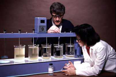
Jar testing is the most effective way to simulate clarification chemistry and operation. A multiple-paddle, beaker arrangement (Figure 5-4) permits the comparison of various chemical combinations, all of which are subjected to identical hydraulic conditions. The effects of rapid and slow mix intensity and duration may also be observed.
In addition to determining the optimum chemical program, it is possible to establish the correct order of addition. The most critical measurements in the jar test are coagulant and/or flocculant dosages, pH, floc size and settling characteristics, floc-forming time, and finished water clarity. To simulate sludge circulation, sludge formed in one series of jar tests (or a sludge sample from an operating clarifier) may be added to the next jar test. Results of jar tests are only relative, and frequent adjustments are necessary in full-scale plant operation. Monitoring and control units, such as a streaming current detector, can be used for on-line feedback control.
Zeta potential measurements have been used experimentally to predict coagulant requirements and optimum pH levels. Because the measurement technique requires special apparatus and a skilled technician, zeta potential has never become practical for controlling industrial water clarification plants. Also, because zeta potential measures only one aspect of the entire process, it may not reflect all conditions leading to coagulation efficiency.
Chemical Additions
The most efficient method for adding coagulation chemicals varies according to the type of water and system used, and must be checked by means of jar testing. However, there is a usual sequence:
- chlorine
- bentonite (for low-turbidity waters)
- primary inorganic and/or polymer coagulant
- pH-adjusting chemicals
- coagulant aid
Waters with a high organic content exhibit an increased primary coagulant demand. Chlorine may be used to assist coagulation by oxidizing organic contaminants which have dispersing properties. Chlorination prior to primary coagulant feed also reduces the coagulant dosage. When an inorganic coagulant is used, the addition of pH-adjusting chemicals prior to the coagulant establishes the proper pH environment for the primary coagulant.
All treatment chemicals, with the exception of coagulant aids, should be added during very turbulent mixing of the influent water. Rapid mixing while the aluminum and iron coagulants are added ensures uniform cation adsorption onto the suspended matter.
High shear mixing is especially important when cationic polymers are used as primary coagulants. In general, it is advisable to feed them as far ahead of the clarifier as possible. However, when a coagulant aid is added, high shear mixing must be avoided to prevent interference with the polymer's bridging function. Only moderate turbulence is needed to generate floc growth.
Figure 5-1. Clarifier and zones.
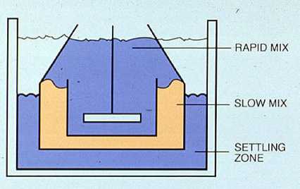
Figure 5-2. Upflow sludge blanket clarifier. (Courtesy of the Permutit Company, Inc.)
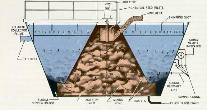
Figure 5-3. Solids-contact clarifier. (Courtesy of Infilco Defremont, Inc.)
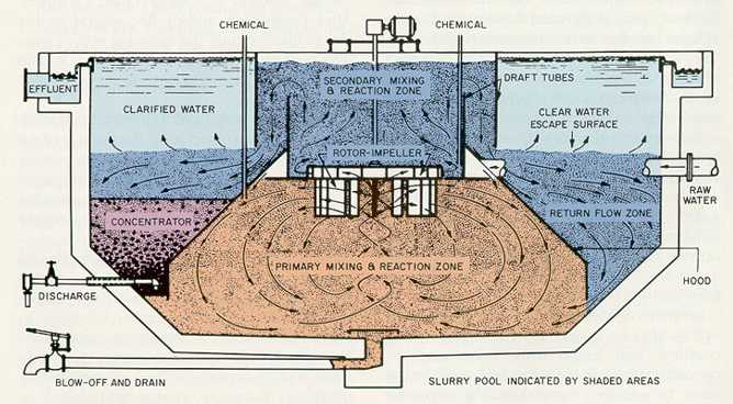
Figure 5-4. Jar test coagulation study.