
- Deaerator Cracking
- Feedwater Line Erosion
- Economizer Tubes
- Failures Due to Overheating
- Failures Due to Corrosion
Successful, reliable operation of steam generation equipment requires the application of the best available methods to prevent scale and corrosion. When equipment failures do occur, it is important that the cause of the problem be correctly identified so that proper corrective steps can be taken to prevent a recurrence. An incorrect diagnosis of a failure can lead to improper corrective measures; thus, problems continue.
There are times when the reasons for failures are obscure. In these instances, considerable investigation may be required to uncover the causes. However, in most cases the problem area displays certain specific, telltale signs. When these characteristics are properly interpreted, the cause of a problem and the remedy become quite evident.
In numerous deaerators, cracks have developed at welds and heat-affected zones near the welds. The cracking most commonly occurs at the head-to-shell weld below the water level in the storage compartment. However, it may also occur above the water level and at longitudinal welds. Because cracks can develop to the point of equipment failure, they represent a potential safety hazard requiring periodic equipment inspection and, when warranted, repair or replacement. Wet fluorescent magnetic particle testing is recommended for identification of cracks.
The mechanism of most deaerator cracking has been identified as environmentally assisted fatigue cracking. Although the exact causes are not known, steps can be taken to minimize the potential for cracking (e.g., stress-relieving of welds and minimization of thermal and mechanical stress during operation). In addition, water chemistry should be designed to minimize corrosion.
High-velocity water and especially water/steam mixtures cause erosion in feedwater systems. The most commonly encountered erosion problems occur at the hairpin bends in steaming economizers. Here, the mixture of steam and water thins the elbows, leaving a characteristic reverse horseshoe imprint.
Similar problems can be encountered in feedwater lines where high velocities create the familiar thinning pattern. These problems can occur even at moderate average flow velocities when a sequence of bends causes a significant increase in local velocity.
In order to mitigate erosion problems, it is helpful to maintain water chemistry conditions that form the most tenacious oxide layer. However, the problems cannot be completely resolved without design or operational changes.
Water tube economizers are often subject to the serious damage of oxygen pitting (see Figure 14-1). The most severe damage occurs at the economizer inlet and, when present, at the tube weld seams. Where economizers are installed, effective deaerating heater operation is absolutely essential. The application of a fast-acting oxygen scavenger, such as catalyzed sodium sulfite, also helps protect this vital part of the boiler.
While oxygen pitting is the most common form of waterside corrosion that causes economizer tube failures, caustic soda has occasionally accumulated under deposits and caused caustic gouging. Usually, this type of attack develops in an area of an economizer where steam generation is taking place beneath a deposit and free caustic soda is present in the feedwater. The best solution to this problem is improved treatment that will eliminate the deposition.
Other common causes of economizer failure include fatigue cracking at the rolled tube ends and fireside corrosion caused by the condensation of acid from the boiler flue gas.
When tube failures occur due to overheating and plastic flow (conditions commonly associated with deposits), the cause is usually identified by the deposits which remain, as shown in Figure 14-2. An accurate analysis of the deposits indicates the source of the problem and the steps needed for correction. Metallographic analyses are useful, at times, in confirming whether a short- or long-term exposure to overheating conditions existed prior to failure. Such analyses are helpful also when metal quality or manufacturing defects are suspected, although these factors are significant only in isolated instances.
When tube failures occur due to overheating, a careful examination of the failed tube section reveals whether the failure is due to rapid escalation in tube wall temperature or a long-term, gradual buildup of deposit. When conditions cause a rapid elevation in metal temperature to 1600°F or above, plastic flow conditions are reached and a violent rupture occurs. Ruptures characterized by thin, sharp edges are identified as "thin-lipped" bursts (see Figure 14-3).
Violent bursts of the thin-lipped variety occur when water circulation in the tube is interrupted by blockage or by circulation failure caused by low water levels. In some steam drum designs, water level is extremely critical because the baffling may isolate a generating section of the boiler when the steam drum water level falls below a certain point.
Thin-lipped bursts also occur in superheater tubes when steam flow is insufficient, when deposits restrict flow, or when tubes are blocked by water due to a rapid firing rate during boiler start-up.
Interruptions in flow do not always result in rapid failure. Depending on the metal temperature reached, the tube can be damaged by corrosive or thinning mechanisms over a long period of time before bulges or blisters or outright failures develop. In such instances, a metallurgical examination in addition to an examination of the contributing mechanical factors can be helpful in identifying the source of the problem.
A long-term scaling condition which will lead to a tube leak is usually indicated by a wrinkled, bulged external surface and a final thick-lipped fissure or opening. This appearance is indicative of long-term creep failure created by repetitive scale formation, causing overheating and swelling of the tube surface in the form of a bulge or blister. The scale, in such instances, tends to crack off; water contacts the metal and cools it until further scaling repeats the process. The iron oxide coating on the external surface cracks during the process, giving rise to the characteristic longitudinal creep cracks.
Stress Corrosion Cracking
Various corrosion mechanisms contribute to boiler tube failure. Stress corrosion may result in either intercrystalline or transgranular cracking of carbon steel. It is caused by a combination of metal stress and the presence of a corrosive. A metallurgical examination of the failed area is required to confirm the specific type of cracking. Once this is determined, proper corrective action can be taken.
Caustic Embrittlement
Caustic embrittlement, a specific form of stress corrosion, results in the intercrystalline cracking of steel. Intercrystalline cracking results only when all of the following are present: specific conditions of stress, a mechanism for concentration such as leakage, and free NaOH in the boiler water. Therefore, boiler tubes usually fail from caustic embrittlement at points where tubes are rolled into sheets, drums, or headers.
The possibility of embrittlement may not be ignored even when the boiler is of an all-welded design. Cracked welds or tube-end leakage can provide the mechanism by which drum metal may be adversely affected. When free caustic is present, embrittlement is possible.
An embrittlement detector may be used to determine whether or not a boiler water has embrittling tendencies. The device, illustrated in Figure 14-4, was developed by the United States Bureau of Mines. If boiler water possesses embrittling characteristics, steps must be taken to protect the boiler from embrittlement-related failure.
Sodium nitrate is the standard treatment for inhibiting embrittlement in boilers operating at low pressures. The ratios of sodium nitrate to sodium hydroxide in the boiler water recommended by the Bureau of Mines depend on the boiler operating pressure. These ratios are as follows:
|
Pressure,psi |
NaNO3 /NaOH Ratio |
|
Up to 250 |
0.20 |
|
Up to 400 |
0.25 |
|
Up to 1000 |
0.40-0.50 |
The formula for calculating the sodium nitrate/sodium hydroxide ratio in the boiler water is:
| NaNO3 | = | ppm nitrate (as NO3 -) |
| NaOH |
ppm M alkalinity - ppm phosphate (as CaCO3 ) (as PO4 3-) |
At pressures above 900 psig, coordinated phosphate/pH control is the usual internal treatment. When properly administered, this treatment method precludes the development of high concentrations of caustic, eliminating the potential for caustic embrittlement.
Fatigue and Corrosion Fatigue
Transgranular cracking primarily due to cyclic stress is the most common form of cracking encountered in industrial boilers. In order to determine the cause of a transgranular failure, it is necessary to study both the design and the operating conditions of the boiler. Straight tube, shell-and-tube waste heat boilers frequently develop tube and tube sheet failures due to the imposition of unequal stresses. A primary cause of this is the uneven distribution of hot gases across the face of the tube sheet. The tubes involved tend to come loose, creating leakage problems. Even when the tubes are securely welded, imposed stresses can cause transverse cracking of the tubes.
Any design feature that allows steam pockets to form within a unit can cause cyclic overheating and quenching. This can lead to transverse cracking of tubes and, occasionally, shells. Such cracking always appears in the area of greatest stress and results in cracks that are primarily transgranular.
Some intercrystalline cracking may develop in this type of failure whether or not free NaOH is present. However, the predominant type of cracking is across the grain structure of the metal. Because it is mechanically induced, the cracking occurs irrespective of boiler water chemical concentrations. The cracks are often accompanied by a number of pits adjacent to or in line with the cracking- another specific indicator of the mechanical stresses imposed. Any corrosives present contribute to the formation of the pits. The normal reaction between iron and water is sufficient to cause pitting at breaks in the thin oxide film formed on freshly exposed surfaces under stress.
Stress-Induced Corrosion
Certain portions of the boiler can be very susceptible to corrosion as a result of stress from mechanical forces applied during the manufacturing and fabrication processes. Damage is commonly visible in stressed components, such as rolled tube ends, threaded bolts, and cyclone separators. However, corrosion can also occur at weld attachments throughout the boiler (see Figure 14-5) and can remain undetected until failure occurs. Regular inspection for evidence of corrosion, particularly in the windbox area of Kraft recovery boilers, is recommended because of the potential for an explosion caused by a tube leak.
The potential for stress-induced corrosion can be reduced if the following factors are minimized: stresses developed in the boiler components, the number of thermal cycles, and the number of boiler chemical cleanings. In addition, it is necessary to maintain proper water chemistry control during operation and to provide protection from corrosion during shutdowns.
Dissolved Oxygen
Dissolved oxygen corrosion is a constant threat to feedwater heater, economizer, and boiler tube integrity. As deposit control treatment methods have improved, the need for effective control of oxygen has become increasingly important.
The first serious emphasis on oxygen control began when phosphate-based treatments were introduced to replace the soda ash treatments common before that time. The dense, hard calcium carbonate scale which developed with the soda ash treatments protected tubes and drums from serious oxygen corrosion. With the application of phosphate treatment, the tube and drum surfaces were cleaner. Therefore, more of the surface area was exposed to corrosives in the water. This spurred the use of improved open feedwater heaters to remove most of the oxygen prior to the entrance of water into the boiler. Today, most plants are equipped with efficiently operated deaerating heaters. The use of oxygen scavengers, such as catalyzed sodium sulfite, hydrazine, and organic scavengers, is also standard practice.
The use of chelant treatments and demineralized water has improved the cleanliness of boiler heat transfer surfaces to such an extent that essentially bare-metal conditions are common. Only a thin, protective, magnetic oxide film remains in such instances. As a result, oxygen control has become even more essential today. The use of catalyzed sulfite, where applicable, is a standard recommendation in chelant applications.
The control of downtime corrosion has become increasingly important in recent years to prevent or inhibit pitting failures. Often, cold water that has not been deaerated is used for rapid cooling or start-up of a boiler. This is a risky operating practice, usually chosen for economical reasons. Severe pitting can occur in such instances, especially in boilers that have been maintained in a deposit-free condition. Therefore, it is usually more economical to maintain clean heat transfer surfaces and eliminate the use of cold water containing dissolved oxygen during cool-down and start-up periods. This practice can result in fuel savings and improved boiler reliability.
Chelant Corrosion
During the early years of chelant use, nearly all internal boiler corrosion problems were labeled "chelant corrosion." However, other corrosives such as oxygen, carbon dioxide, caustic, acid, copper plating, and water are still common causes of boiler corrosion. In addition, mechanical conditions leading to caustic embrittlement, film boiling, and steam blanketing are even more prevalent today than ever, as a result of increasing heat transfer rates and the more compact design of steam generators. Chelant corrosion, or chelant attack, has some specific characteristics, and develops only under certain conditions.
Chelant corrosion of boiler metal occurs only when excess concentration of the sodium salt is maintained over a period of time. The attack is of a dissolving or thinning type-not pitting-and is concentrated in areas of stress within the boiler. It causes thinning of rolled tube ends, threaded members, baffle edges, and similar parts of stressed, unrelieved areas. Normally, annealed tubes and drum surfaces are not attacked. When tube thinning occurs in a chelant-treated boiler, evidence of steam blanketing and/or film boiling is sometimes present. In such instances, failure occurs regardless of the type of internal treatment used.
Pitting is often thought to be a result of chelant attack. However, pitting of carbon steel boiler tubes is almost always due to the presence of uncontrolled oxygen or acid. Infrequently, copper plating (usually the result of an improper acid cleaning operation) may lead to pitting problems.
Caustic Attack
Caustic attack (or caustic corrosion), as differentiated from caustic embrittlement, is encountered in boilers with demineralized water and most often occurs in phosphate-treated boilers where tube deposits form, particularly at high heat input or poor circulation areas. Deposits of a porous nature allow boiler water to permeate the deposits, causing a continuous buildup of boiler water solids between the metal and the deposits.
Because caustic soda does not crystallize under such circumstances, caustic concentration in the trapped liquid can reach 10,000 ppm or more. Complex caustic-ferritic compounds are formed when the caustic dissolves the protective film of magnetic oxide. Water in contact with iron attempts to restore the protective film of magnetite (Fe3O4). As long as the high caustic concentrations remain, this destructive process causes a continuous loss of metal.
The thinning caused by caustic attack assumes irregular patterns and is often referred to ascaustic gouging (see Figure 14-6). When deposits are removed from the tube surface during examination, the characteristic gouges are very evident, along with the white salts deposit which usually outlines the edges of the original deposition area. The whitish deposit is sodium carbonate, the residue of caustic soda reacting with carbon dioxide in the air.
Inspections of boilers with caustic attack often show excessive accumulations of magnetic oxide in low flow areas of drums and headers. This is caused by the flaking off, during operation, of deposits under which the complex caustic-ferritic material has formed. When contacted and diluted by boiler water, this unstable complex immediately reverts to free caustic and magnetic oxide. The suspended and released magnetic oxide moves to and accumulates in low flow or high heat flux areas of the boiler.
While caustic attack is sometimes referred to as caustic pitting, the attack physically appears as irregular gouging or thinning and should not be confused with the concentrated, localized pit penetration representative of oxygen or acid attack.
Steam Blanketing
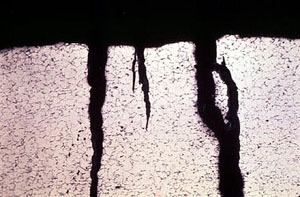
A number of conditions permit stratified flow of steam and water in a given tube, which usually occurs in a low heat input zone of the boiler. This problem is influenced by the angle of the affected tubes, along with the actual load maintained on the boiler. Stratification occurs when, for any reason, velocity is not sufficient to maintain turbulence or thorough mixing of water and steam during passage through the tubes. Stratification most commonly occurs in sloped tubes (Figure 14-7) located away from the radiant heat zone of the boiler, where heat input is low and positive circulation in the tubes may be lacking.
Examination of the affected tubes usually reveals a prominent water line with general thinning in the top area of the tube or crown. In rare instances, the bottom of the tube is thinned. When the boiler water contains caustic, high concentrations accumulate and lead to caustic corrosion and gouging under the deposits that accumulate at the water line.
In certain instances, stratification may occur together with input of heat to the top or crown of the tube. This creates a high degree of superheat in the steam blanket. Direct reaction of steam with the hot steel develops if the metal temperature reaches 750°F or higher. Corrosion of the steel will proceed under such circumstances whether or not caustic is present. When there is doubt about the exact cause, a metallographic analysis will show if abnormal temperature excursions contributed to the problem. Deposits usually found under such circumstances are composed primarily of magnetic iron oxide (Fe3O4). Hydrogen is also formed as a result of the reaction and is released with the steam.
A somewhat unusual problem related to circulation and heat input problems has been encountered in roof tubes. These tubes are usually designed to pick up heat on the bottom side only. Problems generally develop when the tubes sag or break away from the roof, causing exposure of the entire surface of the tube to the hot gases. The overheating that usually develops, along with the internal pressure, causes a gradual enlargement of the tube, sometimes quite uniformly. Failure occurs when the expanded tube can no longer withstand the combined effects of the thermal stress and internal pressure.
Superheater tubes often show the same swelling or enlargement effect. In such instances, steam flow has been restricted for some reason, leading to overheating and eventually to failure.
Acidic Attack
Acid attack of boiler tubes and drums is usually in the form of general thinning of all surfaces. This results in a visually irregular surface appearance, as shown in Figure 14-8. Smooth surfaces appear at areas of flow where the attack has been intensified. In severe occurrences, other components, such as baffling, nuts and bolts, and other stressed areas, may be badly damaged or destroyed, leaving no doubt as to the source of the problem.
Severe instances of acid attack can usually be traced to either an unsatisfactory acid cleaning operation or process contamination. Some industrial plants encounter periodic returned condensate contamination, which eliminates boiler water alkalinity. Occasionally, regeneration acid from an ion exchange process is discharged accidentally into the boiler feedwater system. Cooling water contamination of condensate can depress boiler water pH and cause severe deposition and pitting in areas of high heat flux. Damage can be quite severe if immediate steps are not taken to neutralize the acid.
In the case of industrial process contamination, it is possible for organic contaminants to decompose under boiler temperature and pressure to form organic acids. Sugar is an excellent example of an organic which, when returned in a large quantity, can cause rapid loss of boiler water alkalinity and reduce pH of the boiler water to 4.3 and lower. Most sugar refining plants maintain standby pumping systems, to add caustic soda to neutralize these acids as quickly as possible.
Corrosion Due to Copper
Pitting of boiler drums and tube banks has been encountered due to metallic copper deposits, formed during acid cleaning procedures which do not completely compensate for the amount of copper oxides in the original deposits. Dissolved copper may be plated out on freshly cleaned steel surfaces, eventually establishing anodic corrosion areas and forming pits very similar in form and appearance to those caused by oxygen.
In such instances, metallic copper plating is quite evident. In most cases, it is localized in certain tube banks, giving rise to random pitting in those particular areas. Whenever deposits are found containing large quantities of copper or its oxide, special precautions are required to prevent the plating out of copper during cleaning operations.
Copper deposits and temperatures over 1600°F can cause liquid metal embrittlement. Weld repair of a tube containing copper deposits leads to the failure shown in Figure 14-9.
Hydrogen Attack or Embrittlement
Since around 1960, hydrogen attack, or embrittlement, has been encountered with increasing frequency in high-pressure, high-purity systems. It is not encountered in the average industrial plant because the problem usually occurs only in units operating at pressures of 1500 psig or higher.
In systems of this type, the alkalinity of the boiler water is maintained at values that are quite low compared to usual standards for lower-pressure operation. At the operating pressures indicated and water conditions imposed, either coordinated pH/phosphate or total volatile programs are used. Because the boiler water is relatively unbuffered, total volatile programs are more affected by contaminants that may lower boiler water alkalinity or pH.
When contaminants lower the boiler water pH sufficiently, the acid attack of the steel generates hydrogen. If this occurs under hard, adherent, nonporous tube deposits, the hydrogen pressure within the deposit can build up to the point at which the hydrogen penetrates the steel tubing.
When atomic hydrogen permeates the metal structure, it reacts with the carbon content to form methane. Because the methane molecule is too large to diffuse through the steel, excessive pressure develops within the metal structure, causing the metal to rupture along the crystalline boundaries where methane has formed. The cracking that develops is primarily intercrystalline or intergranular in nature, the metallic area affected becoming decarburized in the process. Failure occurs when the ruptured section can no longer withstand the internal pressure. Ruptures are violent and sudden, and can be disastrous (see Figure 14-10). Failed sections of tubing are cracked in the intergranular mode and decarburized, but usually retain the original dimensions or thickness of the tubing material.
Although there are many causes of low boiler water pH, it most frequently occurs when brackish water is used for condenser cooling. Small quantities of magnesium chloride, in particular, have caused extremely low pH excursions, requiring very close supervision and detection of very low levels of contamination in the condensate.
To summarize, hydrogen embrittlement occurs only when a hard, dense scale is present on the tube surfaces, permitting hydrogen to concentrate under the deposit and permeate the metal. Acidic contamination or low pH excursions commonly produce the conditions for generation of hydrogen. This type of attack may develop very quickly; therefore, constant surveillance of condensate purity is required.
As indicated, hydrogen embrittlement usually occurs in high-purity systems that operate at 1500 psig or higher. Although it is sometimes confused with intergranular creep cracking, this type of failure can be positively identified by the distinctive intergranular nature of the cracking and decarburized condition of the metal.
Surveys of units operating at these pressures and under these conditions have generally indicated that the application of a coordinated pH/phosphate control will lessen the possibility of hydrogen embrittlement. This is due primarily to the improved buffering of the boiler water with phosphate present.
Superheater Tubes
Superheater tube failures are caused by a number of conditions, both mechanical and chemical. In any instance of superheater tube failure, analysis of the deposits found is an important factor in solving the problem. Magnetic oxide deposits at the point of failure are a direct indication of oxidation of the tube metal (see Figure 14-11). This oxidation occurs during overheating where metal temperatures exceed the design temperature and the steel enters into a direct reaction with the steam to form magnetic iron oxide with hydrogen release. When the deposits found in the area of failure are primarily iron oxide, it may be necessary to explore a number of operating conditions in order to determine the initial cause.
Oxidation may occur if the flow of steam through the tubes is restricted or if the heat input is excessive, permitting overheating. In the case of insufficient steam flow, the restriction may be due to conditions prevalent during the transition periods of boiler start-up or shutdown. This occurs if adequate precautions have not been taken to protect the superheater during the transition periods. At no time should gas temperatures exceed 900°F in the area of the superheater until the boiler is up to operating pressure and all superheater tubes are clear of any water which may have accumulated during the downtime. Overheating conditions may develop during times of low-load operation when adequate distribution of saturated steam across the tube bank at the inlet header has not been achieved.
Soluble-salt deposits may form at a superheater tube inlet as a result of excessive entrainment of boiler water solids with the steam. This can result in restricted flow. However, overheating and direct oxidation failures may occur in areas distinctly removed from the blockage, such as the bottom loops or the hottest areas of the superheater tubes.
In some cases, there is a very clear delineation between oxidation products in the hot area and soluble-salts deposits at the inlet. However, in most occurrences, a high percentage of sodium salt deposits is found in the hot areas along with the oxidation products. There is little doubt in such instances that boiler water carryover has contributed to the problem.
Periodic overheating of superheaters, caused by insufficient control of firebox temperatures during start-up and shutdown periods, usually results in thick-lipped fissures and blistering with all the evidence of creep failure. As in the case of water tubes, a superheater tube will fail rapidly (often violently) when flow is blocked for a short period of time and tube temperature escalates rapidly to plastic flow temperatures. Determination of whether a failure is due to a long- or short-term situation depends essentially on the same general characteristics that apply to water tube examination.
Oxygen pitting of superheater tubes, particularly in the pendant loop area, is rather common and occurs during downtime. It is caused by the exposure of water in these areas to oxygen in the air.
It is essential that the manufacturer's instructions be followed rigidly to prevent overheating problems during start-up or shutdown and to prevent oxygen corrosion during downtime.
When soluble-salts deposits are found in superheater tubes, steam purity is of paramount concern. It has been the experience of Betz Laboratories, after conducting thousands of steam purity studies over many years, that soluble-salts deposits in superheaters can be expected, with attendant problems, whenever steam solids exceed 300 ppb. Therefore, when soluble-salts deposits are found, a thorough investigation of steam purity (and reasons for poor purity) is necessary.
Boiler Design Problems
Certain basic design flaws can contribute to tube failures. Problems which occur as a result of a design flaw may be intensified by the boiler water chemistry. The boiler water often contains elements that become corrosive when concentrated far beyond normal values as a result of design problems.
Many industrial boilers, for example, are treated in such a manner that low concentrations of caustic soda are present in the boiler water. The caustic can become corrosive to steel when the boiler water is allowed to concentrate to abnormally high values as a result of poor design. Even in the absence of caustic, conditions which permit stratification or steam blanketing and localized elevation of metal temperatures in excess of 750°F allow direct oxidation or corrosion of the steel in contact with water or steam. This causes loss of metal and eventual rupture of the tube.
Roof tubes, nose arch tubes, and convection pass tubes with slopes of less than 30 degrees from the horizontal are more subject to deposition and stratification problems and tube failures than vertical tubes. Whenever chelant is present in boiler water, the sodium salts of ethylenediaminetetraacetic acid (EDTA), in particular, are destroyed at high temperature, leaving a residue of caustic soda. The caustic soda residue from the chelant is usually an insignificant additive to whatever caustic may be present normally.
A frequent contributor to waste heat boiler problems is the uneven distribution of gases across the inlet tubes at the hot end. This causes unequal stresses and distortion and leads to mechanical stress and fatigue problems.
The use of horizontal hairpin tube configurations with inadequate forced circulation of water through the tubes often permits stratification of steam and water. This often leads to steam blanketing or caustic corrosion problems.
Procedures for Boiler Tube Failure Analysis
At times, the cause of a failure cannot be readily determined, making it difficult to determine the appropriate corrective action. A detailed examination of the failure and associated operating data is usually helpful in identifying the mechanism of failure so that corrective action may be taken.
Proper investigative procedures are needed for accurate metallurgical analyses of boiler tubes. Depending on the specific case, macroscopic examination combined with chemical analysis and microscopic analysis of the metal may be needed to assess the primary failure mechanism(s). When a failed tube section is removed from a boiler, care must be taken to prevent contamination of deposits and damage to the failed zones. Also, the tube should be properly labeled with its location and orientation.
The first step in the lab investigation is a thorough visual examination. Both the fireside and the waterside surfaces should be inspected for failure or indications of imminent failure. Photographic documentation of the as-received condition of tubing can be used in the correlation and interpretation of data obtained during the investigation. Particular attention should be paid to color and texture of deposits, fracture surface location and morphology, and metal surface contour. A stereo microscope allows detailed examination under low-power magnification.
Dimensional analysis of a failed tube is important. Calipers and point micrometers are valuable tools that allow quantitative assessment of failure characteristics such as bulging, wall thinning at a rupture lip, and corrosion damage. The extent of ductile expansion and/or oxide formation can provide clues toward determining the primary failure mechanism. External wall thinning from fireside erosion or corrosion mechanisms can result in tube ruptures which often mimic the appearance of overheating damage. In those cases, dimensional analysis of adjacent areas can help to determine whether or not significant external wall thinning occurred prior to failure. A photograph of a tube cross section taken immediately adjacent to a failure site can assist in dimensional analysis and provide clear-cut documentation.
The extent, orientation, and frequency of tube surface cracking can be helpful in pinpointing a failure mechanism. While overheating damage typically causes longitudinal cracks, fatigue damage commonly results in cracks that run transverse to the tube axis. In particular, zones adjacent to welded supports should be examined closely for cracks. Nondestructive testing (e.g., magnetic particle or dye penetrant inspection) may be necessary to identify and assess the extent of cracking.
When proper water chemistry guidelines are maintained, the waterside surfaces of boiler tubes are coated with a thin protective layer of black magnetite. Excessive waterside deposition can lead to higher-than-design metal temperatures and eventual tube failure. Quantitative analysis of the internal tube surface commonly involves determination of the deposit-weight density (DWD) value and deposit thickness. Interpretation of these values can define the role of internal deposits in a failure mechanism. DWD values are also used to determine whether or not chemical cleaning of boiler tubing is required. In addition, the tube surface may be thoroughly cleaned by means of glass bead blasting during DWD testing. This facilitates accurate assessment of waterside or fireside corrosion damage (e.g., pitting, gouging) that may be hidden by deposits.
The presence of unusual deposition patterns on a waterside surface can be an indication that nonoptimal circulation patterns exist in a boiler tube. For example, longitudinal tracking of deposits in a horizontal roof tube may indicate steam blanketing conditions. Steam blanketing, which results when conditions permit stratified flow of steam and water in a given tube, can lead to accelerated corrosion damage (e.g., wall thinning and/or gouging) and tube failure.
When excessive internal deposits are present in a tube, accurate chemical analyses can be used to determine the source of the problem and the steps necessary for correction. Whenever possible, it is advisable to collect a "bulk" composition, by scraping and crimping the tube and collecting a cross section of the deposit for chemical analysis. Typically, a loss-on-ignition (LOI) value is also determined for the waterside deposit. The LOI value, which represents the weight loss obtained after the deposit is heated in a furnace, can be used to diagnose contamination of the waterside deposit by organic material.
In many cases, chemical analysis of a deposit from a specific area is desired. Scanning electron microscope-energy dispersive spectroscopy (SEM-EDS) is a versatile technique that allows inorganic chemical analysis on a microscopic scale. SEM-EDS analyses are shown in Figures 14-12 and 14-13. For example, SEM-EDS can be useful in the following determinations:
- differences in deposit composition between corroded and noncorroded areas on a tube surface
- the extent to which under-deposit concentration of boiler salts on heat transfer surfaces is promoting corrosion damage
- elemental differences between visually different tube surface deposits
Inorganic analyses through SEM-EDS can also be performed on ground and polished cross sections of a tube covered with thick layers of waterside deposit. This testing is called elemental mapping and is particularly valuable when the deposits are multilayered. Similar to the examination of rings on a tree, cross-sectional analysis of boiler deposits can identify periods when there have been upsets in water chemistry, and thereby provides data to help determine exactly how and when deposits formed. With elemental mapping, the spatial distribution of elements in a deposit cross section is represented by color-coded dot maps. Separate elements of interest can be represented by individual maps, or selected combinations of elements can be represented on composite maps.
A scanning electron microscope (SEM) can also be utilized to analyze the topography of surface deposits and/or morphology of fracture surfaces. Fractography is particularly helpful in classifying a failure mode. For example, microscopic features of a fracture surface can reveal whether the steel failed in a brittle or ductile manner, whether cracks propagated through grains or along grain boundaries, and whether or not fatigue (cyclic stress) was the primary cause of failure. In addition, SEM-EDS testing can be used to identify the involvement of a specific ion or compound in a failure mechanism, through a combination of fracture surface analysis and chemical analysis.
Most water-bearing tubes used in boiler construction are fabricated from low-carbon steel. However, steam-bearing (superheater and reheater) tubes are commonly fabricated from low-alloy steel containing differing levels of chromium and molybdenum. Chromium and molybdenum increase the oxidation and creep resistance of the steel. For accurate assessment of metal overheating, it is important to have a portion of the tube analyzed for alloy chemistry. Alloy analysis can also confirm that the tubing is within specifications. In isolated instances, initial installation of the wrong alloy type or tube repairs using the wrong grade of steel can occur. In these cases, chemical analysis of the steel can be used to determine the cause of premature failure.
At times, it is necessary to estimate the mechanical properties of boiler components. Most often, this involves hardness measurement, which can be used to estimate the tensile strength of the steel. This is particularly useful in documenting the deterioration of mechanical properties that occurs during metal overheating. Usually, a Rockwell hardness tester is used; however, it is sometimes advantageous to use a microhardness tester. For example, microhardness measurements can be used to obtain a hardness profile across a welded zone to assess the potential for brittle cracking in the heat-affected zone of a weld.
Microstructural analysis of a metal component is probably the most important tool in conducting a failure analysis investigation. This testing, called metallography, is useful in determining the following:
- whether a tube failed from short-term or long-term overheating damage
- whether cracks initiated on a waterside or fireside surface
- whether cracks were caused by creep damage, corrosion fatigue, or stress-corrosion cracking (SCC)
- whether tube failure resulted from hydrogen damage or internal corrosion gouging
Proper sample orientation and preparation are critical aspects of microstructural analysis. The orientation of the sectioning is determined by the specific failure characteristics of the case. After careful selection, metal specimens are cut with a power hacksaw or an abrasive cut-off wheel and mounted in a mold with resin or plastic. After mounting, the samples are subjected to a series of grinding and polishing steps. The goal is to obtain a flat, scratch-free surface of metal in the zone of interest. After processing, a suitable etchant is applied to the polished metal surface to reveal microstructural constituents (grain boundaries, distribution and morphology of iron carbides, etc.)
Metallographic analysis of the mounted, polished, and etched sections of metal is performed with a reflective optical microscope (Figure 14-14). This is followed by a comparison of microstructures observed in various areas of a tube section-for example, the heated side versus the unheated side of a waterwall tube. Because the microstructure on the unheated side often reflects the as-manufactured condition of the steel, comparison with the microstructure in a failed region can provide valuable insight into the degree and extent of localized deterioration (Figure 14-15).
Learn more about Veolia's boiler water treatment chemical products and how they can help you reduce boiler system failures.
Figure 14-1. Economizer tube severely damaged by oxygen.
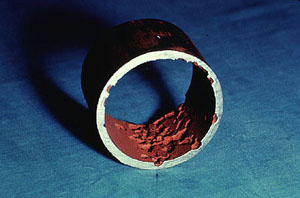
Figure 14-2. Deposit accumulation restricted heat transfer, leading to long-term overheating.
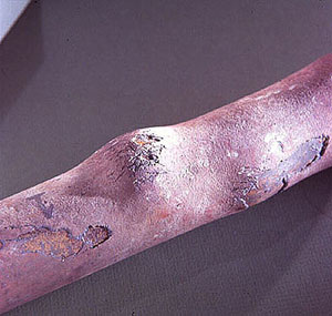
Figure 14-3. Thin-lipped burst caused by rapid overheating.
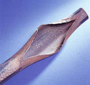
Figure 14-4. Embrittlement detector.
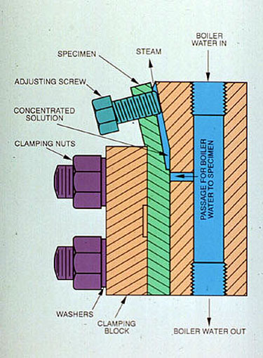
Figure 14-5. Stress at a weld attachment caused localized corrosion.
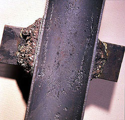
Figure 14-6. Typical gouging caused by caustic attack developed under an original adherent deposit. Note irregular depressions and white (Na2CO3) deposits remaining around edges of original deposit area.
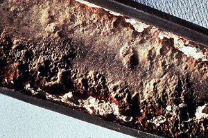
Figure 14-7. Steam blanketing caused metal wastage on top of sloped tube.
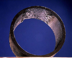
Figure 14-8. Boiler tube shows effect of acid attack.
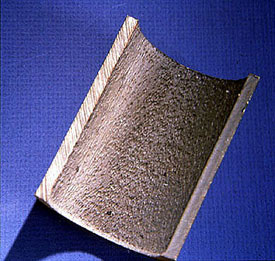
Figure 14-9. Liquid metal embrittlement of boiler tube caused by copper deposits and high temperature (greater than 1600 °F).
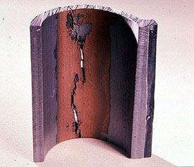
Figure 14-10. Violent rupture caused by hydrogen embrittlement.
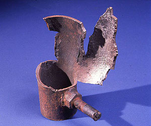
Figure 14-11. Oxygen intrusion during shutdowns caused this pitting of superheater.
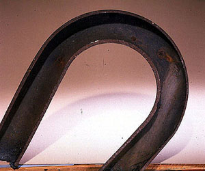
Figure 14-12. Scanning electron microscope (SEM) reveals crystalline structure of highly reflective precipitated magnetite on boiler tube surface. 500X.
Figure 14-14. A reflective optical microscope is used to compare the microstructures of metal specimens.
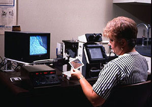
Figure 14-15. Typical photomicrographs for carbon steel boiler tubing.
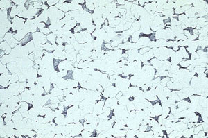 (a) Normal carbon steel tube metal microstructure. ASTM A178-73 Grade "A" tubing. |
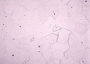 (b) Grain growth caused by overheating of carbon steel. Temperature in the range of 1575 °F and higher. |
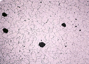 (c) Carbide spheroidization and graphitization indicating very long mild overheatingin the 900-1025 °F range. |
 (d) Transgranular cracking of tubing due to thermal cyclic stress. |