- Feed System Components
- Delivery Systems
- Chemical Feed Systems
- Chemical control Systems
- Cooling System Treatment
- Boiler System Chemical Feed
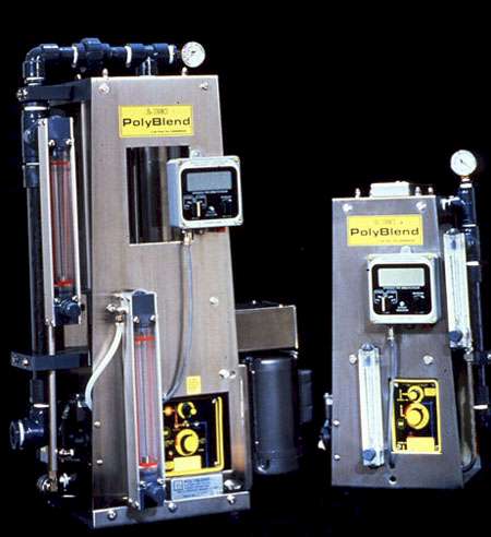
- Water Treatment Polymer Feed Systems
A well engineered feed system is an integral part of an effective water treatment program. If a feed system is not designed properly, chemical control will not meet specifications, program results may be inadequate, and operating costs will probably be excessive. Some of the costly problems associated with poor chemical control include:
- high chemical costs due to overfeed problems
- inconsistent product quality, reduced throughput, and higher steam and electrical costs due to waterside fouling
- high corrosion rates and resultant equipment maintenance and replacement (i.e., plugging or replacing corroded heat exchanger tubes or bundles)
- high labor costs due to an excessive requirement for operator attention
- risk of severe and widespread damage to process equipment due to poor control or spillage of acid into cooling towers
A significant investment in a chemical feed system can often be justified when compared with the high cost of these control problems. When a chemical feed system is not properly engineered, chemical levels are often above or below program specifications. The use of a proper feed system can prevent this situation.
Chemical feed systems can be classified according to the components used, the type of material to be fed (powder or liquid), the control scheme employed, and the application.
Chemical Storage
Treatment chemicals are usually delivered and stored in one of three ways: bulk, semibulk, and drums. The choice among these three depends on a number of factors, including usage rate, safety requirements, shipping regulations, available space, and inventory needs.
Bulk Storage. Large users often find it advantageous to handle their liquid chemical delivery and storage in bulk. Liquid treatments are delivered by vendor tank truck or common carrier. A large tank, often supplied by the water treatment company for storing the liquid treatment, is placed on the property of the user near the point of feed (Figure 35-3). Service representatives often handle all inventory management functions.
Treatment can be drawn from these storage vessels and injected directly into the water system or added to a smaller, secondary feed tank, which serves as a day tank. Day tanks are used as a safeguard to prevent all of the material in the main storage tank from accidentally being emptied into the system. They also provide a convenient way to measure daily product usage rates.
Semibulk Storage. Where chemical feed rates are not large enough to justify bulk delivery and storage, chemicals can be supplied in reusable shuttle tanks (Figure 35-4). Usually, these tanks are designed in such a way that they can be stacked or placed on top of a permanent base tank for easy gravity filling of the base tank.
Drum Storage. Although 40 and 55 gallon drums were widely used for chemical delivery only a few years ago, increasing environmental concerns have sharply reduced drum usage. The restrictions on drum disposal and drum reclamation have reduced the popularity of this delivery and storage method in favor of reusable or returnable containers.
Delivery systems are the heart of a chemical feed system. The delivery system most often used is the chemical metering pump. Nearly 95% of all feed systems use metering pumps. However, gravity feed is gaining popularity in cooling water systems. Eductors are also used occasionally.
Metering Pumps
The most frequently used metering pumps for water treatment applications are the packed plunger, piston, and diaphragm pumps. Rotary gear and progressive cavity pumps are also used occasionally. These all fall under the general heading of "positive displacement pumps."
Design and selection of a metering pump and piping circuit are critical to ensure that pump output will match specifications. Parameters that must be considered include suction side static head, net positive suction head (NPSH), pump turndown, potential syphoning, pressure relief, and materials compatibility.
In order to ensure accurate pumping, operating conditions must be close to design specifications. For example, with a plunger pump, an increase in discharge line pressure can significantly reduce pump output. Because many factors affect pump performance, output should be checked frequently with a calibration cylinder. Some computerized chemical feed systems automatically verify metering pump output and make adjustments as necessary.
Packed Plunger Pumps. Because plunger pumps can be designed for high discharge pressures, they are often used for chemical treatment in boiler systems. Pumping action is produced by a direct-acting piston or plunger that moves back and forth in a reciprocating fashion and directly contacts the process fluid within an enclosed chamber. Motor speed and/or stroke length may be used to adjust this type of pump. The useful working range for packed plunger pumps is approximately 10-100% of rated capacity.
Packed plunger pumps use packing rings to form a seal between the plunger and the plunger bore. In some circumstances, this can necessitate periodic adjustment or replacement of the rings.
Diaphragm Pumps. Diaphragm pumps are becoming increasingly popular in water treatment applications. The diaphragm design uses the reciprocating action of a piston or plunger to transmit pressure through a hydraulic fluid to a flexible diaphragm. The diaphragm isolates and displaces the pumped fluid and is activated either mechanically or hydraulically.
Figure 35-6 shows a diaphragm pump that uses an electronic pulsing circuit to drive a solenoid, which provides the diaphragm stroke. Both stroke length and stroke frequency can be adjusted to provide a usable control range of 10-100% of capacity. Diaphragm pumps can be set up for automatic adjustment of stroke frequency based on an external signal. This capability is commonly used to control the ratio of chemical feed to water flow rate.
The diaphragm pump illustrated in Figure 35-7 uses an internal hydraulic system to operate the diaphragm in contact with the treatment solution. The pump is available in models operating at discharge pressures exceeding 1500 psig. The delivery rate of the pump is manually adjustable while the pump is running and can also be adjusted automatically by a pneumatic or electric control signal. The internal hydraulic system has a built-in valve to protect against overpressure.
Some diaphragm pumps can be used to feed heavy or viscous materials, such as slurries and polymers. Figure 35-8 shows a tubular diaphragm pump that is often used in these applications. The tubular diaphragm design also uses a reciprocating plunger, but a tube-shaped diaphragm expands or contracts with pressure from the hydraulic fluid. Adjustable pumps with flow rates of up to 60 gal/hr at 100 psig are available.
An air-driven diaphragm pump operates from 1 to 200 gpm. This design is usually used for viscous products, and because of its high capacity is generally used to transfer chemical from a storage tank to a day tank. It can be used for feeding shear-sensitive polymer solutions.
The air-driven pump tolerates abrasive materials and is also used to pump sand and sludges. Discharge pressure is limited to approximately 100 psig.
Rotary Pumps. Rotary pumps have one or two rotating members to provide positive or semipositive displacement. The pump may consist of two meshing gears or a single rotating member in an eccentric housing. In the full positive displacement type, delivery rate is fixed by speed of rotation. Semipositive displacement pumps have internal slippage, which affects delivery rate and discharge pressure. Rotary pumps generally depend on the fluid being pumped for lubrication. Most designs will not tolerate abrasive material in the fluid. They can pump highly viscous fluids and are particularly useful for polymer applications, in which low shear is desirable.
Figure 35-9 shows a rotary pump with an idler gear moving inside a rotor gear. Pumping action is achieved by the meshing of rotor and idler gear teeth and by the use of close running tolerances. With every revolution of the pump shaft, a fixed amount of liquid is drawn into the pump through the suction port. This volume of liquid fills the spaces between the teeth of the rotor, progresses through the pump, and is forced out through the discharge port.
Gravity Feed
Another commonly used delivery method, the gravity feed design uses the height difference between chemical in the tank and the point of application as the driving force. The primary advantages of gravity feed delivery are simplicity and reliability. This pumpless design eliminates moving parts and associated maintenance requirements. The elimination of check valves and their periodic failures greatly improves reliability. When feed verification methods are employed, gravity feed can provide precise chemical control.
There are several types of gravity feed systems. A shot feeder is an example of a simple but effective way to dispense premeasured chemical "shots." The shot feeder uses a measuring pot of known volume, which is filled from the bulk stor-age tank. A valve at the bottom of the measuring pot is opened and the product is allowed to flow by gravity into the system.
Feed verification can be achieved by measurement of the velocity of product flow, or volume per time. This permits accurate feed and measurement of product to a system without the traditional maintenance problems associated with metering pumps. The most sophisticated gravity feed systems combine feed verification with computerized controls to provide optimum chemical control and eliminate the need for metering pumps.
Proper size is important. An oversized system will cause spikes in chemical treatment (periodic overfeeds). If the system is undersized, it may not be able to feed enough chemical treatment. Key variables that must be considered in sizing a gravity feed system include product viscosity, available static head, effect of fluctuating tank levels, and system friction losses.
Water-Jet Eductor
The water-jet eductor harnesses the kinetic energy of a moving liquid under pressure. An eductor entrains another liquid, gas, or gas-solid mixture, mixes it with the liquid under pressure, and discharges the mixture against a counterpressure, as shown in Figure 35-10. Application of water-jet eductors is limited by the amount of lift or suction necessary, available motive pressure, and discharge pressure. Generally, a motive-to-discharge pressure ratio of at least 3.5:1 is necessary.
Operated in conjunction with a valve, a water-jet eductor can be used for continuous injection of chemical into a water stream. It is usually used in these applications for mixing rather than proportioning. The water-jet eductor is an important component of vacuum-type chlorinators and sulfonators and is also used for transporting dry polyelectrolytes.
Eductors have many important advantages, including low cost, no moving parts, and the ability to self-prime. Moveover, because electrical power is not needed for operation, eductors are extremely well suited for use in hazardous locations where expensive explosion-proof equipment is required. Eductors can also be adapted to operate with automated control systems.
The accumulation of particulate matter in and around the eductor nozzle can cause a loss of suction. Filters and strainers can assist in reducing this problem. Eductors should be inspected and cleaned periodically in installations where deposition is likely to occur.
Accessories
Pump/Tank Packages. In most applications, a pump alone is not sufficient for chemical feed. Usually, a chemical feed system combines pump, tank, valves, gauges, mixer, strainer and relief valves (to allow chemical solution preparation), mixing (if required), and pumping.
Mixers. A vertically mounted, shaft-driven impeller is the most common type of mixer used for chemical feed systems. If the chemical is a diluted, high molecular weight polymer, a speed reducer may be required. With certain chemicals, it is desirable to minimize air entrainment. In these cases, an electrical or air-driven recirculation pump should be used for mixing.
Timers. Timers find numerous applications in feed systems-most notably, the control of mixers and batch feeding of chemicals (particularly antimicrobials).
Alarms. Alarm systems are becoming more and more sophisticated. It is now possible to monitor and alarm as necessary based on pump status, chemical use rates, high and low tank levels, and unusual operating conditions.
Injection Nozzles. Specialized nozzles are needed to inject chemicals into pipelines. Figures 35-11 and 35-12 show typical low- and high-pressure nozzles. Low-pressure nozzles are used for injection into a liquid stream. High-pressure quill nozzles are used in vapor systems. The quill atomizes the chemical into fine droplets that are carried with the vapor stream. Care should be taken to prevent injection of liquid into steam lines immediately upstream of pipe bends, where high-velocity liquid droplets can impinge upon and erode pipe walls.
Level Gauges. The need to monitor on-site and remote tank levels has led to the development of many different types of level monitors. Among the more prominent methods are pressure transducers, ultrasonic monitors, capacitance sensors, pressure-sensitive linear potentiometers, and bubble tubes. Care must be used to ensure the following:
- compatibility with the materials of construction
- adequate temperature compensation
- isolation from damaging pressure shocks
Liquid Feed
Chemicals may be fed on a "shot" (batch) basis or on a continuous basis. The choice between these two methods depends upon the degree of control required, the application, and the system design.
Shot Feed. Chemical may be shot-fed by on-off control of a chemical feed pump or by discharge from a calibrated vessel or measuring chamber. Shot feeding may be used in cooling systems, bio-oxidation basins, and other places where the system volume to blowdown ratio is large. In these systems, the shot simply replenishes lost or consumed material. Shot feeding is also used in applications that only require periodic feed. Antimicrobials for cooling water systems are usually fed on a shot basis. Shot feed cannot be used in once-through systems, where a uniform concentration of chemical is needed.
Continuous Feed. Continuous feed systems meter chemical to the water constantly. The better systems proportion the feed according to the volume being treated and the chemical demand requirements. Continuous feed is suitable for many systems that can also be shot-fed. It is absolutely necessary in applications such as domestic water chlorination and deposit control in once-through systems, where each gallon of water must be treated and no retention vessel exists. It is also necessary when water clarification chemicals are fed to ensure that all turbidity particles encounter polymer molecules before entering the clarifier.
Continuous feed may be provided by a simple, gravity drip feed method, in which feed rate is regulated by a needle valve. Metering pumps or rotometers and control valves feeding from a recirculating pressurized line (Figure 35-13) can also be used.
Dry Chemical
Large amounts of alum, lime, and soda ash are commonly applied in wastewater treatment plants and large industrial water conditioning plants. Because of the large quantities involved, these additives are usually stored and fed as dry materials. The primary advantage of dry feed is the lower shipping and storage costs. Disadvantages include dust, lack of control, high operational and maintenance costs, and increased operator attention.
Dry feed systems commonly used for water treatment applications include volumetric feeders, gravimetric feeders, and dissolving feeders.
Volumetric Feeders. Volumetric feeders accurately dispense powdered material. The material may be applied directly or used to produce a slurry that is applied to the process. Volumetric feeders are used for lime feed and lime slaking, dry polymer and clay feed, and the feed of fire-side additives to boiler furnaces.
The performance and accuracy of volumetric dry feeders depend largely on the characteristics of the powder being metered. Key characteristics that affect powder feed are particle size distribution, loose and packed bulk densities, moisture content, and abrasiveness.
A typical volumetric feed system includes a bulk storage bin or silo, a feed hopper, and a metering device. The most common metering device is a helical screw or auger. The rotational speed of the screw determines the feed rate.
Some powders tend to bridge, or "rathole," causing uneven feed. To ensure even flow of powder to the helix area, auxiliary devices may be required. Among the more common are flexing hopper walls, bin vibrators, and oversized auxiliary augers positioned above the feed helix.
Gravimetric Feeders. Gravimetric feeders proportion chemicals by weight rather than by volume, and are accurate to within 1-2%. A gravimetric feeder is a scale, balanced to ensure delivery of a desired weight of chemical to the system. The chemical discharged by a gravimetric feeder is usually put into solution or suspension.
Because gravimetric feeders are considerably more expensive than volumetric feeders, they are used only with large systems needing accurate feed or for chemicals whose flow properties prohibit the use of volumetric feeders.
Dissolving Feeders. Dissolving feeders regulate the rate at which a dry chemical is dissolved. A dissolving tank is charged with dry chemical, and a regulated flow of water is fed into the vessel. The concentration of discharged product is governed by the contact area between the dry material and water, and the rate of dissolution. Examples of dissolving feeders include solid halogen feeders and polyelectrolyte dissolving systems.
In some dissolving feeders, extra energy is required to ensure adequate dissolution (wetting) and thorough mixing. For example, in the solid halogen feeder, spray nozzles direct a high-velocity stream of water into the bed of product. In other dissolving feeders, an eductor is used for wetting and mixing.
Automatic and semiautomatic systems have been built to deliver, wet, age, transfer, and feed dry polyelectrolytes (polymers). The delivery and wetting portion of these systems is like that of a dissolving feeder. Either spray curtains (wetting chambers) or eductor devices are used to "wet" the polymer. Various tanks, controls, and pumps are used to agitate, age, transfer, and feed the made-down polymer solution (see Figure 35-14). These feed systems commonly have volumetric screw feeders for precise metering of dry polyelectrolytes. The only manual labor involved is the loading of the bin associated with the volumetric screw feeder.
Another important component of a well engineered chemical feed system is the control scheme-the method by which chemical feed rate adjustments take place. The control scheme can have a dramatic effect on chemical residual control, manpower requirements, and ultimate treatment program results. Key variables that must be considered in the selection of a control scheme include required control range, system half life, dead time, manpower availability, and economics.
Control methods may be classified according to the manner in which the final control element is regulated and the degree of sophistication of the control logic. Typical control schemes used in water treatment applications include: manual, on-off, feedforward, ratio, feedback, and feedforward/feedback combinations. The most sophisticated methods of control require the use of programmable logic controllers or computers.
Manual Control
In a manually controlled system, chemicals are added continuously and at a constant rate. Adjustments are made by plant operators at fixed time intervals-generally once per shift or once per day. These adjustments include pump stroke length or frequency, strength of chemical solution, and valve position.
Manual control is most suitable for applications in which chemical control is not critical, established control ranges are wide, and system retention time is long. In these situations, manual control maintains average chemical balances within acceptable limits.
The disadvantages of manual operation include possible lapses in control, high chemical treatment costs, increased manpower requirements, and the possibility of unacceptable results. With today's emphasis on improved quality control, there is a trend away from manual control and toward the use of more sophisticated equipment.
On-Off Constant Rate Mode
In an on-off control method, a chemical feed pump (or other constant rate feed device) is automatically cycled on and off by a control signal. This method is applicable to systems (e.g., cooling towers) that do not require continuous feed of chemical and have large volume to blowdown ratios.
An example of on-off control is an acid feed pump that turns on at a high pH setpoint and off at a low pH setpoint.
The meter-counter-timer is another on-off control system employed in cooling water systems. In this control method, a chemical pump is turned on for a fixed period of time after a preset volume of makeup water or blowdown has accumulated.
Feedforward Control
Feedforward control systems are designed to detect changes in chemical demand and compensate for them to keep the system under control. In contrast, feedback control systems react only after a system error is detected. Feedforward control is typically used to adjust corrosion inhibitor feed rate (based on changes in water temperature), chelant feed rate (based on a hardness tests), and coagulant feed rate (based on influent turbidity readings).
Ratio Control. Ratio control is a form of feedforward control in which output of the chemical pump or other metering device is automatically adjusted in proportion to a variable, such as water flow rate. Ratio control is most frequently used to maintain a fixed concentration of chemical in a water stream where the flow rate fluctuates. A common example is the feed of corrosion inhibitor in proportion to mill water supply flow rate.
The primary disadvantage of this control scheme is lack of on-line feed verification. Although the controller sends a signal to the pump, there is no guarantee that the metering pump output matches the controller signal or even that the metering pump is working. Recent advances in feedback control technology have provided a solution to this problem.
Feedback Control. With feedback control, the actual value of the controlled variable is continuously compared with the desired value. When the detected value varies from a predetermined setpoint, the controller produces a signal indicating the degree of deviation. In many water treatment applications, this signal is sent to a metering pump and the pump's output is changed.
One of the most common examples of feedback control is the feed of acid to a cooling tower based on pH. When the controller detects a difference between the setpoint and the actual pH, it changes the pump speed or valve position to adjust pH back to the setpoint.
Manual adjustment of a chemical feed pump, based on a boiler water phosphate residual test, is a simple form of feedback control. The accuracy of this method is limited only by the frequency of testing, the time required to affect a change, and the reliability of the monitoring technique.
The main disadvantage of feedback control is the fact that control action does not occur until an error develops. Another key problem with feedback control is that it is highly dependent upon the analyzer signal. In many systems, analyzer accuracy and reliability are questionable.
Most open recirculating cooling systems require the addition of four classes of chemicals to minimize corrosion, scaling, and fouling: corrosion inhibitors
- corrosion inhibitors
- deposit control agents or dispersants
- antimicrobials
- pH adjustment chemicals
Blowdown control is also an integral part of cooling water chemistry management.
Chemical Feed
Corrosion inhibitors and deposit control agents are often fed neat (undiluted) to a cooling tower basin. Common methods for chemical delivery include metering pumps and programmed gravity feed systems. Gravity feed systems may employ water-jet eductors to carry chemicals to the basin. Acids or alkalies used for pH control and some antimicrobials require dilution prior to injection into the bulk cooling water.
Feed pumps can provide accurate continuous feeding, provided that the pump rates are modulated to reflect system changes. Because of the large ratio of cooling water system volume to blowdown rate, periodic shot feed of chemical can often provide satisfactory chemical control.
Inhibitors and Dispersants. Inhibitors and dispersants may be fed neat to the cooling tower basin, where dilution in the recirculating water can easily take place. Feed systems vary from a simple continuous pump or periodic shot feed to computerized automatic control.
The two simplest feed systems in use are continuously operating chemical feed pumps and timed periodic shot feed systems. These methods provide adequate control in some cases, but are inexact if cooling system operating conditions or chemistry vary. When conditions vary, the plant operator must become an integral part of the control loop, testing chemical residuals and adjusting chemical feed rates in order to maintain proper inhibitor and dispersant levels in the water.
For improved chemical control, chemical may be fed in proportion to the flow signal from a blowdown or makeup water flowmeter. This can be done on a continuous basis with a flow signal directly controlling the pumping rate. It can also be done on a semicontinuous basis by a flow counter, which triggers a shot feed of chemical.
Additional improvement in control is possible with computerized controllers that use measured parameters to calculate cycles of concentration and combine that information with real-time flow data to calculate and feed the proper amounts of inhibitor and dispersant.
pH Control. Control of cooling water pH and alkalinity within a specified range is usually required for proper performance of the treatment program. Good pH control has become more important because chromate inhibitor treatment programs are being replaced and higher cycles are being used in cooling towers to minimize blowdown.
Commercial concentrated sulfuric acid (66° Baume) is usually used for cooling water pH control. When fed neat, it is nearly twice as dense as water and drops to the bottom of the cooling tower basin. This can damage basin concrete and cause poor pH control. For this reason, the acid should be well mixed with water prior to entering the basin. A dilution trough is used to feed acid to the cooling tower basin, using makeup water as the diluent.
Mild steel tanks are usually used to store concentrated sulfuric acid. Proper ventilation is required to prevent the buildup of explosive hydrogen gas in the storage tank. Strainers upstream of acid pumps are advisable to remove any residual corrosion products or other solids that may be present in the storage tank.
Feedback control is almost always used to control acid feed to a cooling system. The control schemes most often used are on-off and proportional-integral-derivative (PID). Metering pumps or control valves are normally used to regulate the feed of acid. The location of the pH probe is critical; in most applications, the probe should be placed close to the circulating water pumps.
Proper design is important in acid feed line installation. The lines should be installed so that slow filling and draining, which would cause excessive lag time in the control loop, are prevented. Horizontal sections should slant slightly upward in the direction of flow. Installation of an elevated loop at the discharge end of the line, higher than the acid pump, ensures a continuously filled line. In installations where the acid storage tank is higher than the feed point, an anti-siphon device can be used to provide extra protection against acid overfeed. Concentrated acid feed lines generally need to be no larger than in. and are usually made of 304 or 316 stainless steel tubing. Polyethylene or schedule 80 rigid PVC pipe may be used if protected from physical damage.
Other important considerations include pump/valve size, acid quality, maintenance procedures, and calibration frequency.
Sulfamic acid, hydrochloric acid, nitric acid (liquids), and sodium bisulfate (solid) may also be used for pH reduction. Sometimes, pH control is linked to chlorine gas feed, because chlorine gas combines with water to form hydrochloric acid along with the antimicrobial hypochlorous acid. This practice is not recommended, because overchlorination can result.
If increased alkalinity is needed, soda ash or caustic soda is normally used.
Blowdown Control
Cooling water dissolved solids (measured by conductivity) are maintained at a specified level by a continuous or intermittent purge (blowdown) of the recirculating water. In certain cases, it is sufficient to blow down periodically by opening a valve until the conductivity of the water in the tower reaches a certain specified level. Improved control can be obtained with an automatic blowdown controller, which opens and closes the blowdown valve based on conductivity limits or modulates a blowdown control valve to maintain a conductivity setpoint.
Even more accurate dissolved solids control can be attained when computerized control systems are used. The measured conductivity of the recirculating water divided by that of the makeup water provides an estimate of the cycles of concentration. The recirculating water conductivity setpoint is then adjusted by the on-line computer to maintain the desired number of cycles.
Computerized Chemical Feed and Control Systems
Computerized cooling water chemistry control systems can incorporate some or all of the control functions already discussed in this section, including inhibitor and dispersant feed, pH control, blowdown and cycles control, and nonoxidizing antimicrobial feed. Figure 35-15 is a schematic of a computerized cooling water chemical feed, monitoring, and control system setup.
Computerized control systems can usually be programmed to feed chemicals or adjust operating parameters according to complex customized algorithms. This allows the feed system to compensate automatically for changing operating conditions that are often highly plant-specific. For example, in some cases the makeup water may contain varying amounts of corrosion inhibitor. The corrosion inhibitor feed rate to the recirculating water must be adjusted to compensate for the inhibitor entering the system with the makeup. In other instances, the dispersant feed rate setpoint may need to be adjusted according to system water chemistry (e.g., pH, conductivity, or calcium levels). In each of these cases, a computer can be used to perform the necessary calculations and implement the adjustments automatically.
Some computerized systems provide verification of chemical feed amounts. Combined with on-line chemistry monitoring and customized control algorithms, feed verification permits the most precise treatment control. The measurement system identifies the water chemistry. The computer then calculates needed chemical dosages, and the feed system verifies the quantity of chemical feed. A commonly used system is shown in Figure 35-16.
Remote computers are used to monitor and store cooling system status and program results. Parameters of interest usually include recirculating and makeup water pH and conductivity, chemical feed rates, corrosion rates, and fouling data. Following data collection, statistical techniques are used to analyze treatment program performance.
Modems are incorporated into some computerized feed systems so that alarm conditions trigger an automatic telephone call to the proper operating personnel and advise them of the problem. This prevents minor problems from becoming serious. For example, if a valve is inadvertently left open and the contents of the acid tank begin to drain into the cooling tower basin, a low-pH alarm is activated, and a call is placed automatically to the system operator, who returns to the area and shuts off the valve. Modems are also used to allow operating personnel to make adjustments to system operating parameters and chemical feed rates from a remote location.
For best results, all chemicals for internal treatment of a steam generating facility must be fed continuously and at proper injection points. Chemicals may be fed directly from the storage tank (neat) or may be diluted in a day tank with high-purity water. Certain chemicals may be mixed together and fed from the same day tank.
Chemical feed points are usually selected as far upstream in the boiler water circuit as possible. For chemical feed beyond the feedwater pump or into the steam drum, the pump must be matched to the boiler pressure. For high-pressure boilers, proper pump selection is critical.
Product Feed Considerations
As shown in Figure 35-17, a steam generating system includes three major components for which treatment is required: the deaerator, the boiler, and the condensate system. Oxygen scavengers are usually fed to the storage section of the deaerator. The boiler internal treatment is fed to the feedwater pump suction or discharge, or to the steam drum. Condensate system feed points also vary, according to the chemical and the objective of treatment. Typical feed points include the steam header or other remote steam lines. Chemical feed may also be fed directly in combination with internal treatment chemicals or oxygen scavengers.
Chemicals
Oxygen Scavengers. Oxygen scavengers are most commonly fed from a day tank to the storage section of the deaerator. Some oxygen scavengers have also been applied in steam headers or condensate piping to reduce oxygen-related corrosion in condensate systems. In utility systems, it is common to feed oxygen scavengers into the surface condenser hotwell. Oxygen scavenger feed rates are based on the level of oxygen in the system plus the amount of chemical addi-tives in the system.
Sulfite. Uncatalyzed sodium sulfite may be mixed with other chemicals. The preferred location for sulfite injection is a point in the storage section of the deaerating heater where the sulfite will mix with the discharge from the deaerating section.
If sulfite is fed alone, the following equipment is needed: 304 stainless steel tank
- stainless steel agitator
- stainless steel relief valve
- iron piping, valves, and fittings
- a pump with machined steel or cast iron liquid end and stainless steel trim
In all cases, an injection quill should be used.
Sulfite shipped as liquid concentrate is usually acidic and, when fed neat, corrodes stainless steel tanks at the liquid level. Tanks must be polyester, Fiberglas, or polyethylene. Lines may be PVC or 316 stainless steel.
Catalyzed Sulfite. Catalyzed sulfite must be fed alone and continuously. Mixing of catalyzed sulfite with any other chemical impairs the catalyst. For the same reason, catalyzed sulfite must be diluted with only condensate or demineralized water. To protect the entire preboiler system, including any economizers, catalyzed sulfite should be fed to the storage section of the deaerating heater.
Caustic soda may be used to adjust the pH of the day tank solution; therefore, a mild steel tank cannot be used. Materials of construction for feed equipment are the same as those required for regular sulfite.
Hydrazine. Hydrazine is compatible with all boiler water treatment chemicals except organics, amines, and nitrates. However, it is good engineering practice to feed hydrazine alone. It is usually fed continuously into the storage section of the deaerating heater. Because of handling and exposure concerns associated with hydrazine, closed storage and feed systems have become standard. Materials of construction are the same as those specified for sulfite.
Organic Oxygen Scavengers. Many organic compounds are available, including hydroquinone and ascorbic acid. Some are catalyzed. Most should be fed alone. Like sulfite, organic oxygen scavengers are usually fed continuously into the storage section of the deaerating heater. Materials of construction are the same as those specified for sulfite.
Internal Treatment Chemicals
There are three major classifications of chemicals used in internal treatment: phosphates, chelants, and polymers. These chemicals may be fed either separately or in combination; in most balanced treatment programs, two or three chemicals are fed together. The preferred feed point varies with the chemical specified. For example, when caustic soda is used to maintain boiler water alkalinity, it is fed directly to the boiler drum. When caustic is used to adjust the feedwater pH, it is normally injected into the storage section of the deaerating heater.
Phosphates. Phosphates are usually fed directly into the steam drum of the boiler, although they may be fed to the feedwater line under certain conditions. Treatments containing orthophosphate may produce calcium phosphate feed line deposits; therefore, they should not be fed through the boiler feed line. Orthophosphate should be fed directly to the boiler steam drum through a chemical feed line. Polyphosphates must not be fed to the boiler feedwater line when economizers, heat exchangers, or stage heaters are part of the preboiler system. If the preboiler system does not include such equipment, polyphosphates may be fed to the feedwater piping provided that total hardness does not exceed 2 ppm.
In all cases, feed rates are based on feedwater hardness levels. Phosphates should be fed neat or diluted with condensate or high-purity water. Mild steel tanks, fittings, and feed lines are appropriate. If acidic phosphate solutions are fed, stainless steel and polyolefin materials are recommended.
Chelants. All chelant treatments must be fed to the boiler feedwater line by means of an injection nozzle at a point beyond the discharge of the boiler feed pumps. If heat exchangers or stage heaters are present in the boiler feed line, the injection point should be at their discharge. Care should be exercised in the selection of metals for high-temperature injection quills.
At feed solution strength and elevated temperatures, chelating agents can corrode mild steel and copper alloys; therefore, 304 or 306 stainless steel is recommended for all feed equipment. Chelant products may be fed neat or diluted with condensate. Chelant feed rates must be carefully controlled based on feedwater hardness, because misapplication can have serious consequences.
Chelants should never be fed directly into a boiler. Stainless steel chemical lines would be required, and chloride or caustic stress corrosion could cause the chelant feed line to fail inside the boiler. Localized attack of boiler metal would then occur. Chelants should not be fed if the feedwater contains a significant level of oxygen.
Polymeric Dispersants. In most applications, polymeric dispersants are provided in a combined product formulation with chelants and/or phosphates. Dilution and feed recommendations for chelants should be followed for chelant-dispersant and chelant-phosphate-dispersant programs. Dilution and feed recom-mendations for phosphates should be followed for phosphate-dispersant programs. These combination programs typically have the best results with respect to boiler cleanliness.
Filming Amines. All filming amines should be fed into steam headers at points that permit proper distribution. A single feed point is satisfactory for some systems. In every case, the steam distribution should be investigated and feed points established to ensure that all parts of the system receive proper treatment.
Filming amines must be mixed with condensate or demineralized water. Water containing dissolved solids cannot be used, because the solids would contaminate the steam and could produce unstable amine emulsions.
Steel tanks have been used to feed filming amines, but some corrosion can occur above the liquid level. The use of stainless steel is recommended. Equipment specifications are the same as those for regular sulfite, except that a vapor-type injection nozzle or quill is required.
Neutralizing Amines. Neutralizing amines may be fed to the storage section of the deaerating heater, directly to the boiler with the internal treatment chemicals, or into the main steam header. Some steam distribution systems may require more than one feed point to allow proper distribution. An injection quill is required for feeding into a steam distribution line.
Neutralizing amines are usually fed based on condensate system pH and measured corrosion rates. These amines may be fed neat, diluted with condensate or demineralized water, or mixed in low concentrations with the internal treatment chemicals. A standard packaged steel pump and tank can be used for feeding.
Computerized Boiler Chemical Feed Systems. Computerized boiler chemical feed systems are being used to improve program results and cut operating costs. These systems can be used to feed oxygen scavengers, amines, and internal treatment chemicals.
A typical system, as shown in Figure 35-18, incorporates a metering pump, feed verification equipment, and a microprocessor-based controller. These systems are often linked to personal computers, which are used to monitor program results, feed rates, system status, and plant operating conditions. Trend graphs and management reports can then be produced to provide documentation of program results and help in troubleshooting.
In many cases, these systems can be programmed to feed boiler treatment chemicals according to complex customized algorithms. For example, chelant feed can be adjusted automatically, based on analyzer or operator hardness test results, boiler feedwater flow, and minimum/maximum allowable product feed rates. Thus, chemical feed precisely matches system demand, virtually eliminating the possibility of underfeed or overfeed.
Feed verification is another important facet of some computerized feed systems. The actual output of the pump is continuously measured and compared to a computer-calculated setpoint. If the output doesn't match the setpoint, the speed or stroke length is automatically adjusted. The benefits of this technology include the elimination of time-consuming drawdown measurements, the ability to feed most chemicals directly from bulk tanks, precise chemical residual control, and minimal manpower requirements.
WATER TREATMENT POLYMER FEED SYSTEMS
Polyelectrolytes used in water treatment systems have certain storage, handling, feeding, and dilution requirements. It is imperative that these materials be fed accurately to prevent underfeeding and overfeeding, which can result in wasted chemical treatment and poor system performance.
Polymer Types
Polymers are available as powders, liquids, and emulsions. Each form has different feeding, handling, and storage requirements.
Dry Polymers. Both cationic and anionic high molecular weight polymers are available in powdered form. These products have the advantage of being 100% polymer, which can minimize shipping and handling costs. However, it is absolutely essential that dry polymer materials be handled and diluted properly to prevent underfeeding and overfeeding.
Solution Polymers. Solution polymers are usually cationic, low molecular weight, high charge density products, and are usually used for clarification of raw water. Solution polymers are easier to dilute, handle, and feed than dry and emulsion polymers. In many cases, predilution of a solution polymer is unnecessary, and the product can be fed directly from the shipping container or bulk storage tank. Solution polymers offer the convenience of neat feed, and they can be diluted to any convenient strength consistent with chemical feed pump output.
Emulsion Polymers. Both cationic and anionic high molecular weight polymers are available as emulsions. An emulsion product allows the manufacturer to provide concentrated liquid polymer formulations that cannot be made in solution form. It is only after the emulsion polymer has "inverted" with water that the polymer is available in its active form. Therefore, these products must be diluted properly prior to use.
Storage
Dry Polymers. Dry polymers are susceptible to caking if stored under highly humid conditions. Caking is undesirable because it interferes with the polymer make-down and dilution process. Therefore, dry polymers should be kept in areas of low humidity, and opened containers of dry material should be sealed prior to restorage. In general, polymer products begin to lose their activity after 1 year of storage. Although this process is gradual, it ultimately affects the cost of chemical treatment. It is highly recommended that polymers be used before their expiration dates.
Solution Polymers. Solution polymers should be stored in an area of moderate temperature to protect them from freezing. Some solution products are susceptible to irreversible damage when frozen. Others exhibit excellent freeze-thaw recovery. In no case should solution polymers be stored at temperatures above 120°F. As solutions, these polymers do not require periodic mixing (to prevent separation) before use. However, some solution polymers have a short shelf life, and inventory should be adjusted accordingly.
Emulsion Polymers. Because emulsion polymers are not true solutions, they separate if allowed to stand for a prolonged period of time. Therefore, emulsion polymers must be mixed prior to use with a drum mixer, tank mixer, or tank recirculation package. A bulk tank or bin recirculation package should be designed to recirculate the tank's contents at least once per day to prevent separation. Emulsion polymers contained in drums should also be mixed daily. Neat emulsion polymer must be protected from water contamination, which causes gelling of the product and can make pumping difficult or impossible. In areas of high humidity, tank vents should be outfitted with a desiccant in order to prevent water condensation within the emulsion storage tank. Even small amounts of condensation can cause significant amounts of product gelling. As with liquid products, emulsion polymers must be protected from freezing and should be stored at temperatures below 120°F.
Dilution and Feeding
Dry Polymers. Dry polymers must be diluted with water before use. Most operations require preparation of polymer dilutions once per shift or daily. Typically, a plant operator is charged with the responsibility of measuring a correct amount of dry polymer into a container. The contents of the container are conveyed to the mixing tank through a polymer eductor. The eductor is a device that uses water pressure to create a vacuum and is designed so that dry polymer particles are wetted individually by the water as they pass through the eductor assembly (Figure 35-19). If dry polymer particles are not wetted individually before introduction into the dilution tank, "fisheyes" (undissolved globules of polymer) will form in the solution tank. Fisheyes represent wasted polymer and cause plugging in chemical feed pumps.
Dry polymer solution strengths must be limited to approximately 0.5-1% or less by weight, depending on the product used. This is necessary to keep the solution viscosity to a manageable level. The mixer employed in the solution tank should not exceed 350 rpm, and mixing should proceed only until all material is dissolved. Normally, a batch of diluted dry polymer should be used within 24 hr of preparation, because the diluted product begins to lose activity after this amount of time.
Automatic dry polymer dilution systems can be used to perform the wetting, diluting, and mixing functions previously described; however, the system must be manually recharged with dry polymer periodically. Although costly, these systems can save appreciable time for plant personnel, and operations are usually more consistent when automatic make-down units are used.
Solution Polymers. Solution polymers may be diluted prior to use or fed neat from a shipping container, bin, or bulk storage tank. Dilution of these products becomes necessary if there is insufficient mixing available to combine the polymer with the water being treated. In-line static mixer dilution systems are acceptable for solution polymers and are the simplest method of solution polymer dilution and feed. A solution polymer can be fed through one of the many commercially available emulsion polymer dilution and make-down systems. However, in general, the use of these systems for solution polymers is not necessary. Solution polymers can be pumped most easily with gear pumps. However, many solution polymers have a viscosity low enough to be pumped by diaphragm chemical metering pumps.
Emulsion Polymers. Emulsion polymers must be diluted before use. Dilution allows the emulsion product to invert and "converts" the polymer to its active state. Proper inversion of emulsion polymers is rapid and effective. Improper inversion of the emulsion polymer can result in loss of activity due to incomplete uncoiling and dissolution of the polymer molecules.
Batch and continuous make-down systems are acceptable for emulsion polymer use. In batch preparation, a plant operator feeds a premeasured amount of neat emulsion product into the agitator vortex of a dilution tank. The product is mixed until it is homogeneous, and then the mixers are shut off. As with dry polymer products, mixer speed should always be below 350 rpm and the mixer should be shut off as soon as the product is homogeneous. This prevents excessive shearing of the polymer molecule and resultant loss of polymer activity. A batch emulsion polymer make-down system is shown in Figure 35-20.
Several manufacturers market continuous emulsion polymer make-down and feed systems. These systems pump neat polymer from the storage container into a dilution chamber, where the polymer is combined with water and fully activated. The polymer-water solution then flows by water pressure to the point of application. Provision is made for secondary in-line dilution water to dilute the polymer further prior to use. These polymer feed systems are by far the easiest and best ways to feed emulsions continuously. Their manufacturers claim a superior ability to invert the polymer molecule over batch tank dilution systems. A commercially available continuous emulsion polymer makedown system is shown in Figure 35-21.
It is not acceptable to use in-line static mixing alone for dilution of emulsion polymers. However, in-line static mixing can be employed for blending secondary dilution water with diluted emulsion product prior to application. Initial dilution of emulsion polymers should be 1% or 2% by weight. This solution strength ensures proper particle-to-particle interaction during the inversion step, which aids in complete inversion.
It is usually desirable to provide secondary dilution water capabilities to emulsion polymer feed systems, because these products tend to be most effective when fed at approximately 0.1% solution strength.
General Recommendations
In addition to the above, some general guidelines apply to the feeding and handling of all water treatment polymers. In areas where the temperature routinely drops below freezing, it is good practice to insulate all polymer feed lines so that feed line freezing does not occur.
For tank batches of diluted polymers, tank mixer speeds of over 350 rpm should not be used. In the preparation of diluted batches of polymer, water should always be added to the tank first. Then, the mixer should be started and the polymer added on top of the water.
Diaphragm metering pumps can be used to pump most polymer solutions. However, due to the viscosity of some products, gear pumps may be necessary. Plastic piping should be used in polymer feed systems; stainless steel is also acceptable. Most polymers are corrosive to mild steel and brass. Extra precautions should be taken to prevent spilling of polymers, because wet polymer spills can become extremely slippery and present a safety hazard. Spills should be covered with absorbent material, and the mixture should be removed promptly and disposed of properly.
Figure 35-1. Results of an improperly designed feed system.
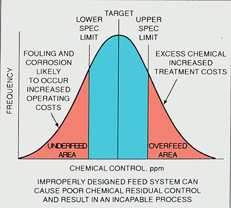
Figure 35-2. Results of a properly designed feed system.
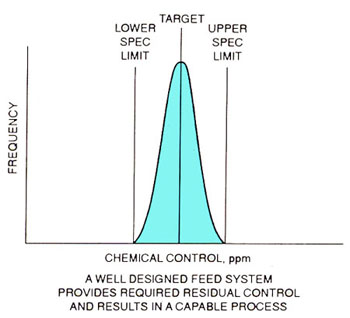
Figure 35-3. Bulk storage tank.
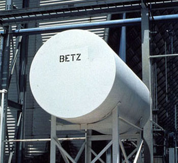
Figure 35-4. Semibulk storage tank.
Figure 35-5. Packed plunger pump. (Reprinted from "Meterng Pumps--Selection and Specification," page 8. Courtesy of Marcel Dekker, Inc.)
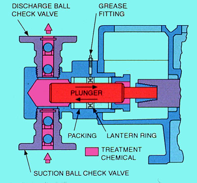
Figure 35-6. LMI diaphragm pump. (Courtesy of Liquid Metronics, Inc.)
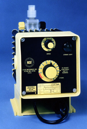
Figure 35-7. Diaphragm pump for high-pressure applications. (Courtesy of Milton Roy Company.)
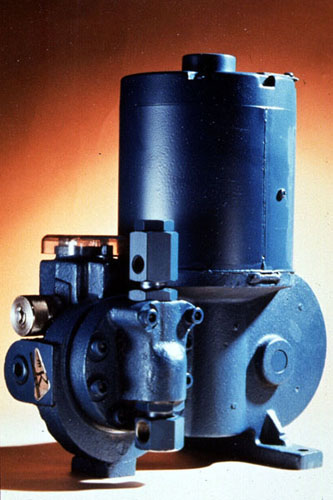
Figure 35-8. Tubular diaphragm pump. (Reprinted from "Metering Pumps--Selection and Specification," page 14. Courtesy of Marcel Dekker, Inc.)
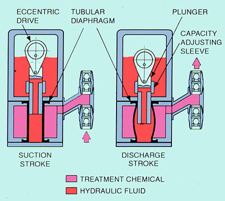
Figure 35-9. Rotary pump. (Courtesy of Viking Pump Div., Houdaille Industries, Inc.)
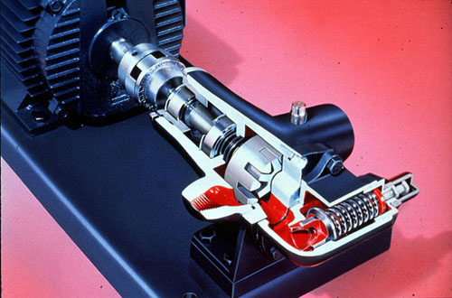
Figure 35-10. Water-jet eductor.
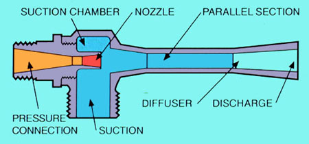
Figure 35-11. Low pressure injection nozzle.
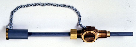
Figure 35-12. High pressure injection nozzle.
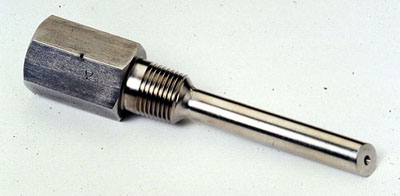
Figure 35-13. Flow diagram of constant-pressure feed using a back-pressure regulator and pump.
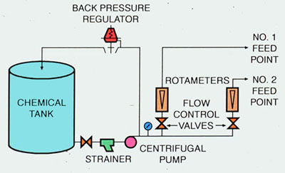
Figure 35-14. Dry polymer feeder.
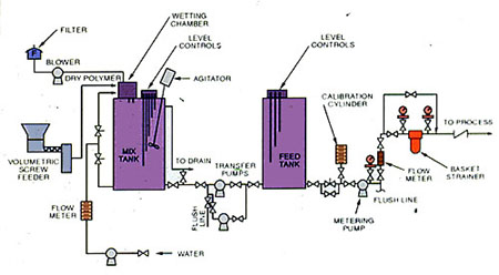
Figure 35-15. Computerized feed system for cooling towers.
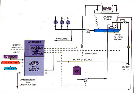
Figure 35-16. System for computerized gravity feed of cooling towers.
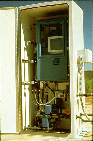
Figure 35-17. Typical piping for boiler system chemical control.
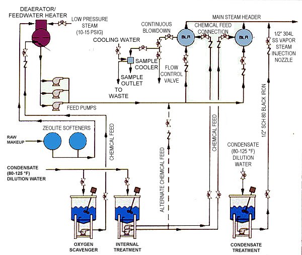
Figure 35-18. Computerized boiler chemical feed system.
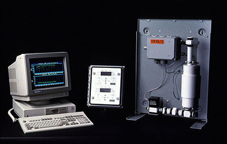
Figure 35-19. Polymer eductor.
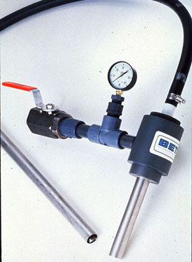
Figure 35-20. Polymer make-down system.
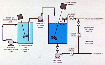
Figure 35-21. Continuous emulsion polymer make-down system.