Most industrial water treatment systems are dynamic. They constantly undergo changes because of seasonal variations in water chemistry, varying plant operating conditions, new environmental laws, and other factors. Because of this, proper monitoring is essential to ensure that the water treatment program applied to a boiler, cooling, wastewater or other industrial water system is satisfactorily controlled so that the desired results are achieved.
Some of the value added benefits obtained through proper monitoring of a water treatment program include:
- reduced risks associated, with chemical underfeed or overfeed
- continuing compliance with environmental regulations
- improved quality of plant operation
- increased water and energy savings
- improved plant productivity
Industrial water treatment systems may be monitored by manual methods or by continuous systems employing automatic instrumentation.
Manual monitoring typically involves plant operators or technicians conducting chemical tests and comparing the results to specified chemical control limits. The testing frequency can vary from once per day to once per hour, depending on the plant resources available. The tests run can include pH, conductivity, suspended solids, alkalinity, hardness, and others. Using the test results, the plant operator manually adjusts a chemical feed pump or blowdown valve, making an estimate of the degree of change necessary.
Manual monitoring is satisfactory for noncritical water systems or systems in which water and plant operating conditions change slowly. Many systems operate with manual monitoring, using the many tests contained in Chapters 39-71 Typical applications include the following:
- closed cooling water treatment systems
- open cooling water systems with consistent makeup water characteristics and steady load conditions
- low to medium pressure boilers
CONTINUOUS, ON LINE MONITORING
Because of the dynamic nature of many water treatment systems and the worldwide need for improved reliability and quality, a higher degree of precision is required in the monitoring and control of water treatment programs than that obtained through manual monitoring. To achieve the degree of precision needed, continuous on-line monitoring with automatic instrumentation is required.
Because of the many technological develop" meets in electronics and microprocessor technology over the last decade, there is a wide range of instrumentation available to monitor water treatment systems. The following sections address the systems available to monitor conductivity. pH, corrosion rate, turbidity, dissolved oxygen. sodium, fouling, biological activity, and halogens.
Specific Conductance
Dissolved solids provide a fundamental measure of water quality. In water, the specific conductance, or ability to carry an electric current, is directly related to the quantity and mobility of the dissolved solids. As such, specific conductance is widely used to monitor boiler makeup and condensate purity and to control boiler and cooling system blowdown.
Recent technological advances have improved the reliability and sophistication of conductivity controllers. Microprocessor based instruments provide extremely reliable and accurate measurement of temperature compensated conductivity combined with sophisticated control modes. The Betz Accutrak® (Figure 36-1) is an example of a conductivity controller. It offers programmable control modes, such as proportional; on/off; and proportional, integral, derivative (PID) control. It also includes self-diagnostics and a display of sensor or electronic fault conditions. Analog and standard communication protocol signals (RS-485) are provided for computer interface, facilitating data acquisition and communication.
In most conductivity measurement systems, two metallic electrodes are immersed in a liquid to complete an electrical circuit. These electrode-type sensors work well in relatively clean water, but lose accuracy if coated by dirt or fouling contaminants, which interfere with the flow of current. To reduce interference from small amounts of contamination in the water, the probe and mounting may be designed to increase the velocity of the flowing sample, minimizing dirt buildup on the electrodes. Electrode-type probes usually show good accuracy in the specific conductance range of 50-8,000 µmho (microsiemens).
Special electrode-type probes are used for contaminant detection in high-purity water, such as steam condensate, demineralized water, and clean water rinses in metal finishing. Measurement over a range of 1-2,000 µmho is practical with these probes.
For heavy fouling conditions (found in some industrial cooling towers and boilers, waste treatment plants, and some processes, such as metal treatment baths) an electrodeless (toroidal) conductivity probe (Figure 36-1) must be used. The toroidal probe uses inductance to sense conductivity changes in a process solution.
pH
pH measurement reveals the hydrogen ion concentration in water. It is used to determine both the deposition and corrosion tendency of a water. The most widely used type of pH measurement is the electrode method. The assembly in Figure 36-2 shows the necessary elements that make up a typical pH sensor: a glass pH electrode, a reference cell, a temperature compensation element, a preamplifier, and a sensor body. Because of the difficulty of maintaining good pH control, manual systems are being replaced by continuous monitoring and automatic control of pH in many water treatment applications. In cooling tower systems, pH has been particularly difficult to control manually because the response curve of pH to acid addition is not linear. Figure 36-3 shows the variation of pH in a cooling tower system with manually adjusted feed of sulfuric acid. Results of random plant tests were plotted to show the number of occurrences of each test value.
pH controllers use much of the same technology as the conductivity controllers discussed above. The Betz Accutrak pH controller (Figure 36-4) uses microprocessor-based electronics, programmable alarm and control modes (such as time proportional control, PID control, self-diagnostics, and a display of electronic or sensor fault conditions), and analog and RS-485 signals for computer interface for data acquisition and communication. pH sensor technology has advanced significantly to overcome many of the problems encountered in the past, such as rapid fouling and chemical attack of the pH electrodes, contamination and rapid depletion of reference cells and electrolytes, and electrical noise and environmental interference with the low-level pH signal.
Several variations of pH sensor assemblies are available for different applications. For relatively clean water, where extensive fouling is not a problem (such as in most cooling towers), a combination pH sensor assembly is normally used. The single, molded body sensor assembly shown in Figure 36-2 combines all of the elements.
Glass electrode deterioration, reference junction plugging, and electrolyte depletion (which occurs in all pH sensor applications) proceed at approximately the same rate. This progression is slow enough in clean water to provide an acceptable economic life. When the combination sensor is worn out, it is discarded.
A rugged, modular pH assembly (Figure 36-5) is used in processes such as metal treatment baths and waste systems, where fouling or chemical attack of glass electrodes, reference junctions, and other elements is a problem. The modular assembly allows periodic maintenance and replacement of individual components.
Corrosion Rate
Corrosion rate instruments are used in many different applications to provide instantaneous corrosion rate values in mils per year. A typical package consists of an analyzer and probes, as shown in Figure 36-6. Corrosion rate instruments are used for critical cooling systems, steam condensate systems, mill water supply streams, and other applications.
Analyzers are available for portable use or continuous operation. Portable units are generally used when several probes are installed in remote locations. The operator connects the analyzer to the probe and takes a reading, and then moves to the next probe. Continuous analyzers are used when a probe is located in a critical area that warrants continuous evaluation. They include recorder and control outputs that can be interfaced with other components such as process controllers and pumps.
Analyzers usually have internal meters and a means of checking calibrations against a standard.
The probe houses the electrodes and exposes them to the test stream. Probes are manufactured in many different configurations. Common configurations include two or three electrodes. Mild steel, stainless steel, and polyvinyl chloride (PVC) are common probe materials. Probes are available as standard and retractable assemblies and are usually provided with standard pipe connections.
Electrodes are made from many different metals, such as stainless steel, mild steel, Admiralty brass, and 90-10 copper-nickel. Electrodes fasten onto the probe, and the probe and electrode assembly are inserted into the test stream.
Turbidity
Turbidity is caused by suspended matter and can be defined as a lack of clarity in water. Turbidity measuring instruments are used to monitor and control clarifiers and lime softeners and to detect corrosion products in steam condensate.
There are presently two methods used for continuous measurement of turbidity-the nephelometric method and surface scatter technique.
Nephelometric method. In the nephelometric method, the sample flows through a cell. Near the midpoint of the cell, a light source sends a beam of light into the moving fluid. Light receivers are located at various positions in the cell. The receivers measure the amount of light scattered 90° from the incident light. The amount of light scattered increases as the turbidity in the sample increases. The instrument measures the scattered light and develops a signal that is related to nephelometer turbidity units (NTU).
Surface Scatter Technique. The surface scatter technique is similar to the nephelometric method in theory of operation. However, in this method a light source emits a beam toward the surface of a constant level reservoir. The reflected and refracted portions of the beam are discarded and the scattered portion is sensed by a photocell. The amount scattered is in direct relationship to the turbidity of the sample. Because the light transmitter and photocell are not in contact with the sample, this method eliminates fouling.
Turbidity measuring instruments usually include an analog or digital readout and a signal output that can be interfaced with a computer or chart recorder. An example of a surface scatter unit is shown in Figure 36-7, and the technique is illustrated in Figure 36-8.
Dissolved Oxygen Instrumentation
The ability to measure dissolved oxygen is very important, especially in boiler systems, where oxygen corrosion can be very damaging.
A typical dissolved oxygen measuring instrument consists of a sensor, a sensor cell, and an analyzer, as shown in Figure 36-9. The sensor measures the dissolved oxygen concentration and transmits a signal, proportional to the oxygen concentration, to the analyzer. The analyzer provides a readout in parts per billion or parts per million and an output that can be connected to a recorder or data logging device.
Dissolved oxygen is commonly measured by a membrane-isolated electrochemical cell. This cell contains a cathode, an anode, and an electrolyte solution. A gas-permeable membrane admits the dissolved oxygen from the sample to the electrodes. There, an electrochemical reaction generates an electric current with a magnitude proportional to the dissolved oxygen concentration. The reaction can be summarized by the following equation:
| O2 | + | 2H2O | + | 4e- | ® | 4OH - |
| dissolvedoxygen | water | electrons | hydroxide ions |
For dissolved oxygen analyzer calibration, the sensor is exposed to humid air. The concentration of dissolved oxygen in the moisture is between 8 and 10 ppm, depending on the ambient pressure and temperature. The analyzer reading is adjusted to the correct value for the pressure and temperature. Some analyzers have an automatic calibration feature that measures the temperature and pressure at the push of a button.
Sodium
Sodium instrumentation has become very important as a means of determining steam purity. To determine the total dissolved solids concentration of the steam, the sodium level in a cooled steam sample is compared to the ratio of total solids to sodium in the boiler water.
The most common technique used to measure sodium is the specific ion electrode. The sodium specific ion electrode responds logarithmically to changes in sodium concentration. The only other factors affecting the readings are temperature and pH. Temperature is measured by an internal thermistor. A reference electrode provides the primary potential signal required for the measurement. Before the sample contacts the electrodes, the sample is circulated through a diffusion tube that is immersed in ammonia; this procedure eliminates hydrogen ion interference.
For calibration of the specific ion analyzer, both electrodes are immersed in a known standard solution. The electrodes are also immersed in another standard with a tenfold higher concentration of sodium ions for determination of the electrode slope. Modern microprocessor technology has provided advanced calibration techniques that verify electrode stability during calibration.
A typical sodium instrument is shown in Figure 36-10.
Fouling
There are several specialty systems designed to monitor the rate of fouling and corrosion in industrial equipment, including those discussed in the following sections.
The MonitAll contains a clear flow-through assembly. Sample water flows in at the bottom and out of the top of a tube. A heat probe is inserted into the flow assembly along the axis of the tube. The heat probe generates an adjustable heat flux across a tubular metal test section. Fouling or corrosion can be accelerated if the heat flux is raised above design levels.
The test section is removable and interchangeable for other metals, which include mild steel, Admiralty brass, 304 stainless steel, 316 stainless steel, and 90-10 copper-nickel.
The heat probe includes two temperature sensors that measure probe surface temperature and bulk water temperature. The temperatures are monitored by a meter with a light-emitting diode (LED) display. The temperature meter has an analog output for a recorder or data logging device.
As the test section fouls, less heat is dissipated into the bulk water and the tube skin temperature decreases. The result is an increase in the temperature difference (DT) which can be related to fouling factor Rf by the following equation:
| Rf = | DTfinal - DTinitial |
| Heat Flux (Btu/hr/ft2) |
The MonitAll is equipped with flow control valves to maintain a constant flow rate and insertion tubes to increase velocity in the clear flow cell.
Model Condenser. The Betz Model Condenser, Figure 36-12, is a test device used primarily to simulate surface condenser fouling and corrosion. It consists of a horizontal, cylindrical stainless steel shell with one, two, or four removable tubes. The tubes run the length of the shell and terminate at the tube sheets. An electric heater is located in the bottom of the shell to generate a constant heat flux. Temperature sensors are located in the shell and tube discharges to monitor temperature difference.
The principle of operation is very similar to that of a standard surface condenser. The test water flows through the tube(s) and discharges to drain. The shell is filled with distilled water, which covers the electric heater but is below the tubes. A vacuum of 27 inches of mercury is applied to the shell to simulate condenser conditions. Heat is applied to the distilled water with the electric heater. The distilled water boils and the vapor rises to the tube surfaces. Cool water flowing through the tubes condenses steam on the tube surfaces. The condensation falls to the reservoir of distilled water and the cycle repeats.
Condenser operating conditions, such as heat flux and tubeside velocity, are simulated by the model condenser. Shell temperature and tube discharge temperature are monitored continuously. As foulant accumulates on the internal tube surfaces, less heat is transferred through the tube wall. As a result, the shell temperature increases and the tube discharge temperature decreases. At a constant flow rate, the increase in the temperature difference can be related to a fouling factor by the same equation given for the MonitAll. Typically, tubes are removed and sent to a laboratory for further analysis.
Test Heat Exchanger. A test heat exchanger (Figure 36-13) is used to monitor the fouling and corrosion tendencies of a particular cooling water stream. Cooling water passes through two remov-able tubes contained in a cylindrical shell. The tubes, which are available in many different materials, can be arranged for two single-pass or one two-pass operation. Steam or hot condensate flows into the shell and heats the water flowing through the tubes. The condensate exits the shell through a flowmeter that is used to monitor heat input.
COSMOS™ Cooling System Monitoring Station. Monitoring and analysis of key operating parameters are important tools in the development of an effective cooling water treatment program. The Betz Cooling System Monitoring Station (COSMOS ) is a versatile tool that can be used for this purpose. It monitors pH, conductivity, and corrosion rates. In addition, a MonitAll® hot tester can be included for evaluation of heat flux, water velocity, and fouling factors. A variety of metals can be evaluated.
The monitoring station consists of two units: a data acquisition cabinet and a piping and instrumentation cabinet. Figure 36-14 shows the data acquisition cabinet, with the panel door open, connected to the piping and instrumentation cabinet.
The piping and instrumentation cabinet (wet side) includes the MonitAll hot tester, a flow sensor, two corrosion probes, a conductivity sensor, a pH sensor, coupon holders, stainless steel piping, and a drain line. A small electrical enclosure within the cabinet supplies the electrical power for the MonitAll and the space heater provided for climate control.
The data acquisition cabinet contains the microprocessor-based controller, which manages all of the data acquisition, storage, and display. It also controls a printer, the floppy disk drive, automatic corrosion probe switching, automatic shutdown safeguards and alarms, and the climate controls. The controller has a keypad and a display window for operator interface. A personal computer can be used to generate reports, graphs, and statistical analysis from the acquired data.
Biological Activity in Cooling Systems
A biofilm fouling monitor (Figure 36-15) is used to determine levels of microorganisms attached to surfaces in a cooling system. The monitor consists of a holder that is threaded on both ends. Each half of the holder contains a screen that secures glass beads to the sampling surfaces.
The biofilm monitor can be attached at any suitable location in the hot water return where the flow through the monitor is at least 1-2 gpm. The monitor is normally on line at least 1 week before the sampling starts. The time required to develop a steady-state biofilm on the beads varies depending on system conditions. Steady-state is reached when the amount of biological material removed by turbulent flow is equal to the amount of new biofilm produced by microbial growth. After steady-state is achieved, changes in levels of biofilm reflect changes in the system environment; for example, increased nutrient levels lead to greater amounts of biofilm, while the addition of toxic materials causes a reduction in biofilm levels. Individual systems must be monitored to determine what level of fixed microorganisms is acceptable.
Macrofouling monitors (Figure 36-16) are used to monitor the growth rate of zebra mussels, Asiatic clams, and other mollusks. The problems caused by these animals are described inChapter 28. The strategic placement of macrofouling control monitors helps to quantify growth and settlement cycles in a particular area. They also provide quantification of kill rates following chemical treatment.
A macrofouling unit contains a set of fouling plates. Water flows upward through the unit. The mussel or clam larvae attach themselves to the fouling plates. Their rate of growth is monitored visually by regular examination of the plates.
Halogen Residuals
Continuous on-line measurement devices used to monitor halogen residuals fall into two categories: amperometric and colorimetric.
Amperometric analyzers, depending on the mode of use, measure free or total halogen concentrations in water samples. Changing halogen concentrations in the sample produce a corresponding change in the electrical current that flows from the cathode to the anode of a sensor. Some amperometric analyzers also correct for variations in sample temperature and pH.
Figure 36-17 shows a colorimetric analyzer, which changes color intensity depending on the chlorine concentration of the sample. Small volumes of sample, an indicator agent, and a buffer solution are precisely metered and mixed. During a development interval, the indicator oxidizes and produces a magenta or red compound which is photometrically measured. The color intensity is compared to a reference and the difference is used to characterize the chlorine concentration of the sample. Measurement accuracy can be affected by the presence of chromates, chloramines, nitrite, iron, manganese, and other strong oxidants in the sample. Careful selection of the chlorine analyzer and proper installation should help to minimize these measurement interferences.
Continuous monitoring is an important part of many chlorine applications:
- to control feed rate in potable water supplies
- to prevent damage to ion exchange demineralizers or reverse osmosis systems in municipal and industrial water supplies
- as an antimicrobial in cooling tower applications
- verifying regulatory discharge requirements for wastewater or industrial process streams
Visual Inspection
Visual inspection equipment is often useful for the inspection of internal surfaces in boiler tubes, condenser tubes, heat exchangers, and turbines. Visual inspection is used to determine failure potential due to deposit accumulation or corrosion.
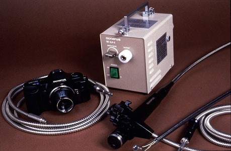
Fiber Optics. A fiber optics device (Figure 36-18) is commonly used for equipment inspection. A lens on each end of the fiber optics bundle provides a clear, undistorted, color image. Video equipment and 35 mm cameras may be used with a fiber optics system.
Video Inspection. Television camera inspection equipment provides an alternative to fiber optics. The typical package consists of a miniature camera, lights, a rotating mirror for radial viewing, and a monitor.
Additional Monitoring Technologies
Ion Chromatography. Ion chromatography (IC) is widely used in laboratories and is finding a place in some continuous process analysis applications. It is used to detect low-level contamination of otherwise high-purity streams. The detection capability of IC permits routine analysis in the parts per billion range and, in some cases, in the parts per trillion range. The advantages of IC are its selectivity, sensitivity, and speed in the analysis of anions and cations.
An ion chromatograph consists of an anion or cation separation column and an anion or cation suppressor column. In the separation process, metals are eluted from a separating resin with a strong acid, such as HCl. The metals are then exposed to the suppressor column, which is a strong anion exchanger in the hydroxide form. The chloride (Cl) is removed by the anion resin and the eluted hydroxide reacts with the acid proton to form H2O. Thus, the metals elute in very dilute water solution as metal hydroxides, and the conductivity is measured. For alkali metals and many other metals, the conductivity imparted to pure water is a simple function of species concentration. Anions are separated in an analogous process.
Flow Injection Analysis. Air-segmented continuous process analyzers have been the foundation of automated industrial water testing for over 30 years. The technology has evolved to a point at which such systems are cost-effective and productive for a wide variety of industrial process monitoring applications. However, in the 1990's, nonsegmented flow injection analysis (FIA) was introduced as an alternative method for these applications.
In the FIA method, small quantities of sample are transported through a narrow bore tube and then mixed with reagents to develop a color that is monitored by a detector. In this new technique, air bubbles are not used to separate individual samples. Samples are injected into a flowing, continuous stream of reagent. To maintain sample integrity, injection intervals must be long enough to prevent cross-contamination. FIA is highly reproducible due to the elimination of air bubbles, the use of precise injection techniques, constant flow rates, and exact timing of analytical reaction from injection to detection.
Figure 36-1. BetzDearborn Accutrak conductivity controller and toroidal probe.
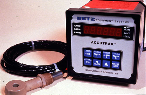
Figure 36-2. Typical pH sensor assembly schematic.
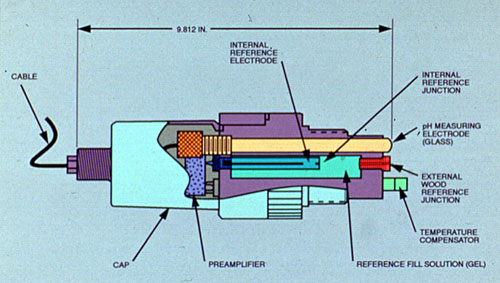
Figure 36-3. Variation of pH in a cooling tower system with manual control.
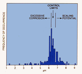
Figure 36-4. BetzDearborn Accutrak pH controller with modular pH sensor.
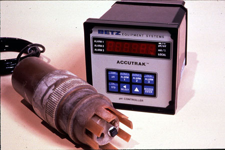
Figure 36-5. Modular pH assembly.
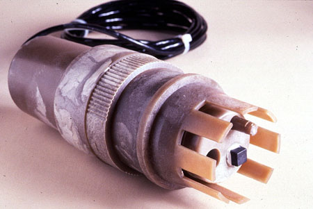
Figure 36-6. Corrater corrosion rate instruments and probes. (Courtesy of Rohrback Cassasco Systems.)
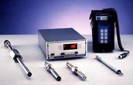
Figure 36-7. Turbidimeter. (Courtesy of Hach Company.)
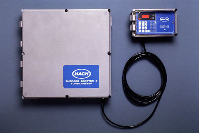
Figure 36-8. Operational diagram of surface scatter technique.
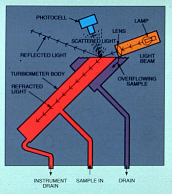
Figure 36-9. dissolved oxygen analyzer. (Courtesy of Orbisphere Laboratories.)
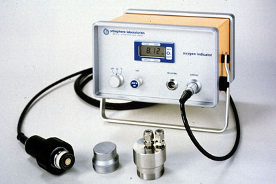
Figure 36-10. Sodium analyzer. (Courtesy of Orion Research, Inc.)
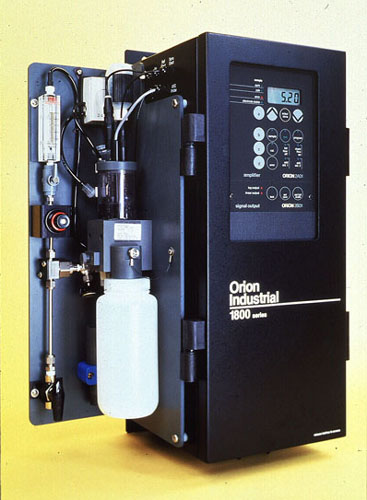
Figure 36-11. BetzDearborn MonitAll portable assembly.
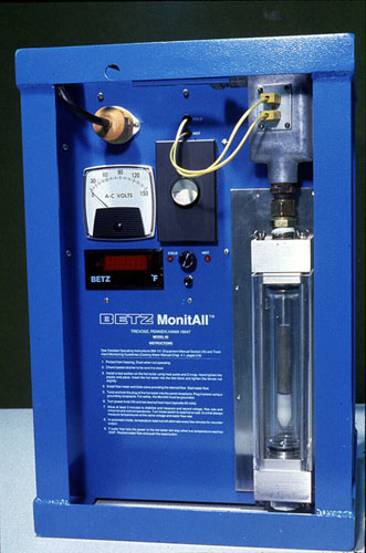
Figure 36-12. BetzDearborn model condenser.
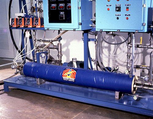
Figure 36-13. Test heat exchanger.
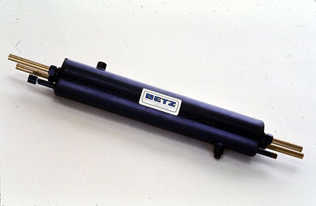
Figure 36-14. BetzDearborn cooling system monitoring station (COSMOS).
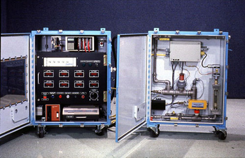
Figure 36-15. Biofilm fouling monitor.
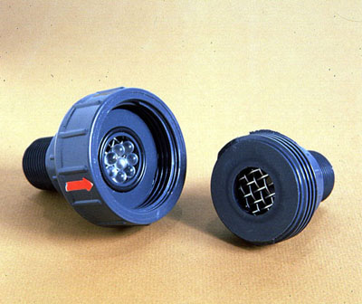
Figure 36-16. Macrofouling monitor.
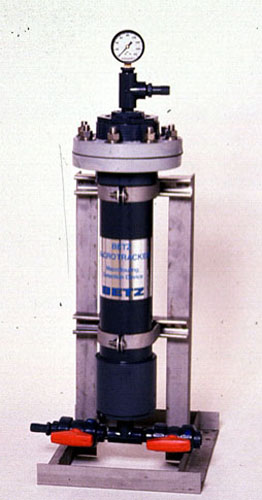
Figure 36-17. Colorimetric-type chlorine analyzer. (Courtesy of Hach Company.)
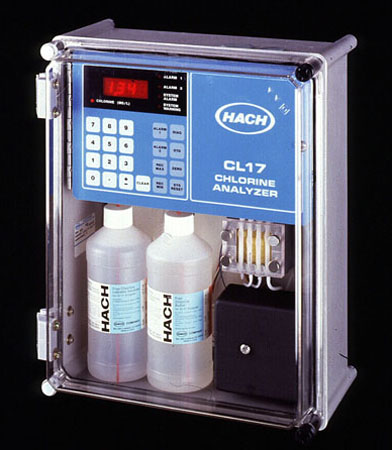
Figure 36-18. Fiber optics visual inspection device.