- History
- Advantages
- Classifications of ion exchange resins
- Sodium zeolite softening
- Hot zeolite softening
- Demineralization
- Dealkalization
- Counterflow and mixed bed deionization
- Other demineralization processes
- Condensate polishing
- Common ion exchange system problems
- Resin fouling and degradation
- Resin testing and analysis
ION EXCHANGE WATER TREATMENT SYSTEM
An ion exchange water treatment system is a specialized technology used in wastewater treatment to remove dissolved ions and contaminants from water. This system relies on ion exchange resins that attract undesirable ions in the wastewater and exchange them with more desirable ions, effectively purifying the water before discharge. Ion exchange water treatment systems play a significant role in wastewater treatment and contribute to improving water quality and meeting various industrial and domestic needs.
All natural waters contain, in various concentrations, dissolved salts which dissociate in water to form charged ions. Positively charged ions are called cations; negatively charged ions are called anions. Ionic impurities can seriously affect the reliability and operating efficiency of a boiler or process system. Overheating caused by the buildup of scale or deposits formed by these impurities can lead to catastrophic tube failures, costly production losses, and unscheduled downtime.
Hardness ions, such as calcium and magnesium, must be removed from the water supply before it can be used as boiler feedwater. For high-pressure boiler feedwater systems and many process systems, nearly complete removal of all ions, including carbon dioxide and silica, is required. Ion exchange systems are used for efficient removal of dissolved ions from water.
Ion exchangers exchange one ion for another, hold it temporarily, and then release it to a regenerant solution. In an ion exchange system, undesirable ions in the water supply are replaced with more acceptable ions. For example, in a sodium zeolite softener, scale-forming calcium and magnesium ions are replaced with sodium ions.
Veolia’s ion exchange products
ION EXCHANGE WATER TREATMENT HISTORY
In 1905, Gans, a German chemist, used synthetic aluminosilicate materials known as zeolites in the first ion exchange water softeners. Although aluminosilicate materials are rarely used today, the term "zeolite softener" is commonly used to describe any cation exchange process.
The synthetic zeolite exchange material was soon replaced by a naturally occurring material called Greensand. Greensand had a lower exchange capacity than the synthetic material, but its greater physical stability made it more suitable for industrial applications. Capacity is defined as the amount of exchangeable ions a unit quantity of resin will remove from a solution. It is usually expressed in kilograins per cubic foot as calcium carbonate.

The development of a sulfonated coal cation exchange medium, referred to as carbonaceous zeolite, extended the application of ion exchange to hydrogen cycle operation, allowing for the reduction of alkalinity as well as hardness. Soon, an anion exchange resin (a condensation product of polyamines and formaldehyde) was developed.
The new anion resin was used with the hydrogen cycle cation resin in an attempt to demineralize (remove all dissolved salts from) water. However, early anion exchangers were unstable and could not remove such weakly ionized acids as silicic and carbonic acid.
In the middle 1940's, ion exchange resins were developed based on the copolymerization of styrene cross-linked with divinylbenzene. These resins were very stable and had much greater exchange capacities than their predecessors. The polystyrene-divinylbenzene-based anion exchan-ger could remove all anions, including silicic and carbonic acids. This innovation made the complete demineralization of water possible.
Polystyrene-divinylbenzene resins are still used in the majority of ion exchange applications. Although the basic resin components are the same, the resins have been modified in many ways to meet the requirements of specific applications and provide a longer resin life. One of the most significant changes has been the development of the macroreticular, or macroporous, resin structure.
Standard gelular resins, such as those shown in Figure 8-1, have a permeable membrane structure. This structure meets the chemical and physical requirements of most applications. However, in some applications the physical strength and chemical resistance required of the resin structure is beyond the capabilities of the typical gel structure. Macroreticular resins feature discrete pores within a highly cross-linked polystyrene-divinylbenzene matrix.
These resins possess a higher physical strength than gels, as well as a greater resistance to thermal degradation and oxidizing agents. Macroreticular anion resins (Figure 8-2) are also more resistant to organic fouling due to their more porous structure.

In addition to polystyrene-divinylbenzene resins (Figure 8-3), there are newer resins with an acrylic structure, which increases their resistance to organic fouling.

In addition to a plastic matrix, ion exchange resin contains ionizable functional groups. These functional groups consist of both positively charged cation elements and negatively charged anion elements. However, only one of the ionic species is mobile. The other ionic group is attached to the bead structure. Figure 8-4 is a schematic illustration of a strong acid cation exchange resin bead, which has ionic sites consisting of immobile anionic (SO3¯) radicals and mobile sodium cations (Na+). Ion exchange occurs when raw water ions diffuse into the bead structure and exchange for the mobile portion of the functional group. Ions displaced from the bead diffuse back into the water solution.

ADVANTAGES AND LIMITATIONS OF ION EXCHANGE
The ion exchange water treatment system is a widely used technology in various applications, including wastewater treatment, due to its numerous advantages and benefits. However, it also comes with certain limitations that need to be considered in specific contexts. Here are the advantages and limitations of the ion exchange process:
Advantages of ion exchange in water treatment:
- Efficient removal of dissolved ions and contaminants, leading to enhanced water quality.
- Versatile and applicable to a wide range of water treatment scenarios.
- Can be customized for specific ion removal needs, making it highly effective in targeted applications.
Limitations of ion exchange in water treatment:
- Limited capacity and lifespan of ion exchange resins, necessitating periodic replacement.
- High operational costs, particularly for large-scale applications or when treating highly contaminated water.
- Potential for regenerant chemicals used in the process to cause environmental concerns during disposal.
Overall, ion exchange remains a valuable and versatile tool in water treatment, but careful consideration of its advantages and limitations is essential for successful implementation in various contexts.
CLASSIFICATIONS OF ION EXCHANGE RESINS
Ionizable groups attached to the resin bead determine the functional capability of the resin. Industrial water treatment resins are classified into four basic categories:
- Strong Acid Cation (SAC)
- Weak Acid Cation (WAC)
- Strong Base Anion (SBA)
- Weak Base Anion (WBA)
SAC resins can neutralize strong bases and convert neutral salts into their corresponding acids. SBA resins can neutralize strong acids and convert neutral salts into their corresponding bases. These resins are utilized in most softening and full demineralization applications. WAC and WBA resins are able to neutralize strong bases and acids, respectively. These resins are used for dealkalization, partial demineralization, or (in combination with strong resins) full demineralization.
SAC resins derive their functionality from sulfonic acid groups (HSO3¯). When used in demineralization, SAC resins remove nearly all raw water cations, replacing them with hydrogen ions, as shown below:

The exchange reaction is reversible. When its capacity is exhausted, the resin can be regenerated with an excess of mineral acid.
Strong acid cation exchangers function well at all pH ranges. These resins have found a wide range of applications. For example, they are used in the sodium cycle (sodium as the mobile ion) for softening and in the hydrogen cycle for decationization.
Weak acid cation exchange resins derive their exchange activity from a carboxylic group (-COOH). When operated in the hydrogen form, WAC resins remove cations that are associated with alkalinity, producing carbonic acid as shown:
These reactions are also reversible and permit the return of the exhausted WAC resin to the regenerated form. WAC resins are not able to remove all of the cations in most water supplies. Their primary asset is their high regeneration efficiency in comparison with SAC resins. This high efficiency reduces the amount of acid required to regenerate the resin, thereby reducing the waste acid and minimizing disposal problems.
Weak acid cation resins are used primarily for softening and dealkalization of high-hardness, high-alkalinity waters, frequently in conjunction with SAC sodium cycle polishing systems. In full demineralization systems, the use of WAC and SAC resins in combination provides the economy of the more efficient WAC resin along with the full exchange capabilities of the SAC resin.
SBA resins derive their functionality from quaternary ammonium functional groups. Two types of quaternary ammonium groups, referred to as Type I and Type II, are used. Type I sites have three methyl groups:
In a Type II resin one of the methyl groups is replaced with an ethanol group. The Type I resin has a greater stability than the Type II resin and is able to remove more of the weakly ionized acids. Type II resins provide a greater regeneration efficiency and a greater capacity for the same amount of regenerant chemical used.
When in the hydroxide form, SBA resins remove all commonly encountered anions as shown below:
As with the cation resins, these reactions are reversible, allowing for the regeneration of the resin with a strong alkali, such as caustic soda, to return the resin to the hydroxide form.
Weak base resin functionality originates in primary (R-NH2), secondary (R-NHR'), or tertiary (R-NR'2) amine groups. WBA resins readily re-move sulfuric, nitric, and hydrochloric acids, as represented by the following reaction:
SODIUM ZEOLITE SOFTENING
Sodium zeolite softening is the most widely applied use of ion exchange. In zeolite softening, water containing scale-forming ions, such as calcium and magnesium, passes through a resin bed containing SAC resin in the sodium form. In the resin, the hardness ions are exchanged with the sodium, and the sodium diffuses into the bulk water solution. The hardness-free water, termed soft water, can then be used for low to medium pressure boiler feedwater, reverse osmosis system makeup, some chemical processes, and commercial applications, such as laundries.
Principles of Zeolite Softening
The removal of hardness from water by a zeolite softening process is described by the following reaction:
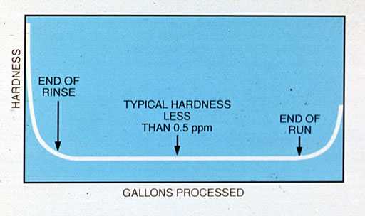
Water from a properly operated zeolite softener is nearly free from detectable hardness. How-ever, some small amounts of hardness, known as leakage, are present in the treated water. The level of hardness leakage is dependent on the hardness and sodium level in the influent water and the amount of salt used for regeneration.
After final rinse, the softener produces a low, nearly constant level of hardness until the ion exchange resin nears exhaustion. At exhaustion, the effluent hardness increases sharply, and regeneration is required (see Figure 8-5).
As illustrated by the softening reactions, SAC resin readily accepts calcium and magnesium ions in exchange for sodium ions. When exhausted resin is regenerated, a high concentration of sodium ions is applied to the resin to replace calcium and magnesium. The resin is treated with a 10% sodium chloride solution, and regeneration proceeds according to the following equation:
![]()
During regeneration, a large excess of regenerant (approximately 3 times the amount of calcium and magnesium in the resin) is used. The eluted hardness is removed from the softening unit in the waste brine and by rinsing.
After regeneration, small residual amounts of hardness remain in the resin. If resin is allowed to sit in a stagnant vessel of water, some hardness will diffuse into the bulk water. Therefore, at the initiation of flow, the water effluent from a zeolite softener can contain hardness even if it has been regenerated recently. After a few minutes of flow, the hardness is rinsed from the softener, and the treated water is soft.
The duration of a service cycle depends on the rate of softener flow, the hardness level in the water, and the amount of salt used for regeneration. Table 8-1 shows the effect of regenerant level on the softening capacity of a gelular strong cation resin. Note that the capacity of the resin increases as the regenerant dosage increases, but the increase is not proportional. The regeneration is less efficient at the higher regenerant levels. Therefore, softener operating costs increase as the regenerant level increases. As shown by the data in Table 8-1, a 150% increase in regenerant salt provides only a 67% increase in operating capacity.
Table 8-1. Effect of regenerant salt level on strong acid cation resin softening capacity.
| Table 8-1. Effect of regenerant salt level on strong acid cation resin softening capacity. | |
| Salt (lb/ft3) | Capacity (gr/ft3) |
| 6 | 18,000 |
| 8 | 20,000 |
| 10 | 24,000 |
| 15 | 30,000 |
Equipment
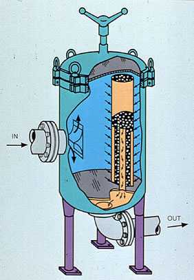
The equipment used for sodium zeolite softening consists of a softener exchange vessel, control valves and piping, and a system for brining, or regenerating, the resin. Usually, the softener tank is a vertical steel pressure vessel with dished heads as shown in Figure 8-6. Major features of the softening vessel include an inlet distribution system, free-board space, a regenerant distribution system, ion exchange resin, and a resin-retaining underdrain collection system.

The inlet distribution system is usually located at the top of the tank. The inlet system provides even distribution of influent water. This prevents the water from hollowing out flow channels in the resin bed, which would reduce system capacity and effluent quality. The inlet system also acts as a collector for backwash water.
The inlet distributor consists of a central header/hub with distributing laterals/radials or simple baffle plates, which direct the flow of water evenly over the resin bed. If water is not prevented from flowing directly onto the bed or tank walls, channeling will result.
The volume between the inlet distributor and the top of the resin bed is called the free-board space. The free-board allows for the expansion of the resin during the backwash portion of the regeneration without loss of resin. It should be a minimum of 50% of the resin volume (80% preferred).
The regenerant distributor is usually a header-lateral system that evenly distributes the regenerant brine during regeneration. The location of the distributor, 6 in. above the top of the resin bed, prevents the dilution of regenerant by water in the free-board space. It also reduces water and time requirements for displacement and fast rinse. The regenerant distributor should be secured to the tank structure to prevent breakage and subsequent channeling of the regenerant.
Water is softened by the bed of strong acid cation exchange resin in the sodium form. The quantity of resin required depends on the water flow, total hardness, and time desired between regeneration cycles. A minimum bed depth of 24 in. is recommended for all systems.
The underdrain system, located at the bottom of the vessel, retains ion exchange resin in the tank, evenly collects the service flow, and evenly distributes the backwash flow. Uneven collection of water in service or uneven distribution of the backwash water can result in channeling, resin fouling, or resin loss.
Although several underdrain designs are used, there are two primary types–subfill and resin-retaining. A subfill system consists of multiple layers of support media (such as graded gravel or anthracite) which support the resin, and a collection system incorporating drilled pipes or subfill strainers.
As long as the support layers remain intact, the resin will remain in place. If the supporting media becomes disturbed, usually due to improper backwash, the resin can move through the disrupted layers and exit the vessel. A resin-retaining collector, such as a screened lateral or profile wire strainer, is more expensive than a subfill system but protects against resin loss.
The main valve and piping system directs the flow of water and regenerant to the proper locations. The valve system consists of a valve nest or a single multiport valve. A valve nest includes six main valves: service inlet and outlet, backwash inlet and outlet, regenerant inlet, and regenerant/rinse drain. The valves may be operated manually, or automatically controlled by air, electrical impulse, or water pressure. In some systems, a single multiport valve is used in place of the valve nest.
As the valve rotates through a series of fixed positions, ports in the valve direct flow in the same manner as a valve nest. Multiport valves can eliminate operational errors caused by opening of the incorrect valve but must be properly maintained to avoid leaks through the port seals.
The brining system consists of salt dissolving/brine measuring equipment, and dilution control equipment to provide the desired regenerant strength. The dissolving/measuring equipment is designed to provide the correct amount of concentrated brine (approximately 26% NaCl) for each regeneration, without allowing any undissolved salt into the resin.
Most systems use a float-operated valve to control the fill and draw-down of the supply tank, thereby controlling the amount of salt used in the regeneration. Usually, the concentrated brine is removed from the tank by means of an eductor system, which also dilutes the brine to the optimum regenerant strength (8-10% NaCl). The brine can also be pumped from the concentrated salt tank and mixed with dilution water to provide the desired regenerant strength.
Softener Operation
A sodium zeolite softener operates through two basic cycles: the service cycle, which produces soft water for use, and the regeneration cycle, which restores resin capacity at exhaustion.
In the service cycle, water enters the softener through the inlet distribution system and flows through the bed. The hardness ions diffuse into the resin and exchange with sodium ions, which return to the bulk water. Soft water is collected in the underdrain system and discharged. Service water flow to the softener should be as constant as possible to prevent sudden surges and frequent on-off operation.
Due to resin requirements and vessel designs, the softening operation is most efficient when a service flow rate between 6 and 12 gpm per square foot of resin surface area is maintained. Most equipment is designed to operate in this range, but some special designs utilize a deep resin bed to permit operation at 15-20 gpm/ft².
Continuous operation above the manufacturer's suggested limits can lead to bed compaction, channeling, premature hardness breakthrough, and hardness leakage. Operating well below the manufacturer's recommended flow rates can also negatively affect softener performance. At low flow rates, the water is not sufficiently distributed, and the optimum resin-water contact cannot take place.
When a softener is exhausted, the resin must be regenerated. Monitoring of the effluent hardness reveals resin exhaustion. When hardness increases, the unit is exhausted. Automatic monitors pro-vide a more constant indication of the condition of the softener than periodic operator sampling and testing, but require frequent maintenance to ensure accuracy. Many facilities regenerate softeners before exhaustion, based on a predetermined time period or number of gallons processed.
Most softening systems consist of more than one softener. They are often operated so that one softener is in regeneration or standby while the other units are in service. This ensures an uninterrupted flow of soft water. Prior to placing a standby softener into service, the unit should be rinsed to remove any hardness that has entered the water during the standing time.
Softener Regeneration
The regeneration cycle of a sodium zeolite softener consists of four steps: backwash, regeneration (brining), displacement (slow rinse), and fast rinse.
Backwash. During the service cycle, the downward flow of water causes suspended material to accumulate on the resin bed. Resin is an excellent filter and can trap particulate matter that has passed through upstream filtration equipment. The backwash step removes accumulated material and reclassifies the resin bed.
In the backwash step, water flows from the underdrain distributor up through the resin bed and out the service distributor to waste. The upward flow lifts and expands the resin, allowing for removal of particulate material and resin fines and the classification of the resin. Resin classification brings the smaller beads to the top of the unit while the larger beads settle to the bottom. This enhances the distribution of the regenerant chemical and service water.
Backwashing should continue for a minimum of 10 min or until effluent from the backwash outlet is clear. The backwash flow should be sufficient to expand the resin bed volume by 50% or more, depending on the available free-board. Insufficient backwash can lead to bed fouling and channeling. Excessive backwash flow rates result in the loss of resin. Backwash flow rates usually vary between 4-8 (ambient temperature) and 12-15 (hot service) gpm per square foot of bed area, but each manufacturer's recommendation should be followed.
The ability of water to expand the resin is greatly affected by temperature. Less flow is required to expand the bed with cold water than with warm water. Resin bed expansion should be checked regularly and the flow rate adjusted as needed to maintain proper bed expansion.
Usually, the backwash water is filtered raw water. Water leaving the backwash outlet is unchanged in chemistry but can contain suspended solids. In order to conserve water, the backwash effluent can be returned to the clarifier or filter influent for treatment.
Regeneration (Brining). After backwash, regenerant brine is applied. The brine stream enters the unit through the regenerant distributor and flows down through the resin bed at a slow rate (usually between 0.5 and 1 gpm per square foot of resin). Brine flow is collected through the underdrain and sent to waste. The slow flow rate increases contact between the brine and resin. To achieve optimum efficiency from the brine, the solution strength should be 10% during brine introduction.
Displacement (Slow Rinse). Following the introduction of regenerant brine, a slow flow of water continues through the regenerant distribution system. This water flow displaces the regenerant through the bed at the desired flow rate. The displacement step completes the regeneration of the resin by ensuring proper contact of the regenerant with the bottom of the resin bed.
The flow rate for the displacement water is usually the same rate used for the dilution of the concentrated brine. The duration of the displacement step should be sufficient to allow for approximately one resin bed volume of water to pass through the unit. This provides a "plug" of displacement water which gradually moves the brine completely through the bed.
Fast Rinse. After completion of the displacement rinse, water is introduced through the inlet distributor at a high flow rate. This rinse water removes the remaining brine as well as any residual hardness from the resin bed. The fast rinse flow rate is normally between 1.5 and 2 gpm per square foot of resin. Sometimes it is deter-mined by the service rate for the softener.
Initially, the rinse effluent contains large amounts of hardness and sodium chloride. Usually, hardness is rinsed from the softener before excess sodium chloride. In many operations, the softener can be returned to service as soon as the hardness reaches a predetermined level, but some uses require rinsing until the effluent chlorides or conductivity are near influent levels. An effective fast rinse is important to ensure high effluent quality during the service run. If the softener has been in standby following a regeneration, a second fast rinse, known as a service rinse, can be used to remove any hardness that has entered the water during standby.
HOT ZEOLITE SOFTENING
The equipment and operation of a hot zeolite softener is identical to that of an ambient temperature softener, except that the valves, piping, controllers, and instrumentation must be suitable for the high temperature (220-250°F). Standard strong cation resin can be used at temperatures of up to 270°F, but for a longer service life a premium gel or macroreticular resin is recommended. When operating a zeolite system following a hot process softener, it is important to design the system to eliminate flow surges in the hot lime unit. Common designs include the use of backwash water storage tanks in the hot lime unit and extended slow rinses for the zeolite in lieu of a standard fast rinse.
Applications and Advantages
Scale and deposit buildup in boilers and the formation of insoluble soap curds in washing operations have created a large demand for softened water. Because sodium zeolite softeners are able to satisfy this demand economically, they are widely used in the preparation of water for low and medium pressure boilers, laundries, and chemical processes. Sodium zeolite softening also offers the following advantages over other softening methods:
- treated water has a very low scaling tendency because zeolite softening reduces the hardness level of most water supplies to less than 2 ppm
- operation is simple and reliable; automatic and semiautomatic regeneration controls are available at a reasonable cost
- salt is inexpensive and easy to handle
- no waste sludge is produced; usually, waste disposal is not a problem
- within certain limits, variations in water flow rate have little effect on treated water quality
- because efficient operation can be obtained in units of almost any size, sodium zeolite softeners are suitable for both large and small installations
Limitations
Although sodium zeolite softeners efficiently re-duce the amount of dissolved hardness in a water supply, the total solids content, alkalinity, and silica in the water remain unaffected. A sodium zeolite softener is not a direct replacement for a hot lime-soda softener. Plants that have replaced their hot process softeners with only zeolite softeners have experienced problems with silica and alkalinity levels in their boilers.
Because the resin is such an efficient filter, sodium zeolite softeners do not function efficiently on turbid waters. Continued operation with an influent turbidity in excess of 1.0 JTU causes bed fouling, short service runs, and poor effluent quality. Most city and well waters are suitable, but many surface supplies must be clarified and filtered before use.
The resin can be fouled by heavy metal contaminants, such as iron and aluminum, which are not removed during the course of a normal regeneration. If excess iron or manganese is present in the water supply, the resin must be cleaned periodically. Whenever aluminum coagulants are used ahead of zeolite softeners, proper equipment operation and close control of clarifier pH are essential to good softener performance.
Strong oxidizing agents in the raw water attack and degrade the resin. Chlorine, present in most municipal supplies, is a strong oxidant and should be removed prior to zeolite softening by activated carbon filtration or reaction with sodium sulfite.
DEMINERALIZATION
Softening alone is insufficient for most high-pressure boiler feedwaters and for many process streams, especially those used in the manufacture of electronics equipment. In addition to the removal of hardness, these processes require removal of all dissolved solids, such as sodium, silica, alkalinity, and the mineral anions (Cl¯, SO4²¯, NO3¯).
Demineralization of water is the removal of essentially all inorganic salts by ion exchange. In this process, strong acid cation resin in the hydrogen form converts dissolved salts into their corresponding acids, and strong base anion resin in the hydroxide form removes these acids. Demineralization produces water similar in quality to distillation at a lower cost for most fresh waters.
Principles of Demineralization
A demineralizer system consists of one or more ion exchange resin columns, which include a strong acid cation unit and a strong base anion unit. The cation resin exchanges hydrogen for the raw water cations as shown by the following reactions:
A measure of the total concentration of the strong acids in the cation effluent is the free mineral acidity (FMA). In a typical service run, the FMA content is stable most of the time (see Figure 8-8).

If cation exchange were 100% efficient, the FMA from the exchanger would be equal to the theoretical mineral acidity (TMA) of the water. The FMA is usually slightly lower than the TMA because a small amount of sodium leaks through the cation exchanger. The amount of sodium leakage depends on the regenerant level, the flow rate, and the proportion of sodium to the other cations in the raw water. In general, sodium leakage increases as the ratio of sodium to total cations increases.
As a cation exchange unit nears exhaustion, FMA in the effluent drops sharply, indicating that the exchanger should be removed from service. At this time the resin should be regenerated with an acid solution, which returns the exchange sites to the hydrogen form. Sulfuric acid is normally used due to its affordable cost and its availability. However, improper use of sulfuric acid can cause irreversible fouling of the resin with calcium sulfate.
To prevent this occurrence, the sulfuric acid is usually applied at a high flow rate (1 gpm per square foot of resin) and an initial concentration of 2% or less. The acid concentration is gradually increased to 6-8% to complete regeneration.
Some installations use hydrochloric acid for regeneration. This necessitates the use of special materials of construction in the regenerant system. As with a sodium zeolite unit, an excess of regenerant (sulfuric or hydrochloric acid) is required up to three times the theoretical dose.
To complete the demineralization process, water from the cation unit is passed through a strong base anion exchange resin in the hydroxide form. The resin exchanges hydrogen ions for both highly ionized mineral ions and the more weakly ionized carbonic and silicic acids, as shown below:
The above reactions indicate that demineralization completely removes the cations and anions from the water. In reality, because ion exchange reactions are equilibrium reactions, some leakage occurs. Most leakage from cation units is sodium. This sodium leakage is converted to sodium hydroxide in the anion units. There-fore, the effluent pH of a two bed cation-anion demineralizer system is slightly alkaline. The caustic produced in the anions causes a small amount of silica leakage. The extent of leakage from the anions depends on the chemistry of the water being processed and the regenerant dosage being used.
Demineralization using strong anion resins removes silica as well as other dissolved solids. Effluent silica and conductivity are important parameters to monitor during a demineralizer service run. Both silica and conductivity are low at the end of the fast rinse (see Figure 8-9).
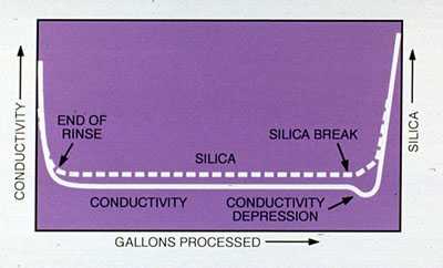
When silica breakthrough occurs at the end of a service run, the treated water silica level increases sharply. Often, the conductivity of the water decreases momentarily, then rises rapidly. This temporary drop in conductivity is easily explained. During the normal service run, most of the effluent conductivity is attributed to the small level of sodium hydroxide produced in the anion exchanger.
When silica breakthrough occurs, the hydroxide is no longer available, and the sodium from the cation exchanger is converted to sodium silicate, which is much less conductive than sodium hydroxide. As anion resin exhaustion progresses, the more conductive mineral ions break through, causing a subsequent increase in conductivity.
When the end of a demineralizer run is detected, the unit must be removed from service immediately. If the demineralizer is allowed to remain in service past the breakpoint, the level of silica in the treated water can rise above that of the influent water, due to the concentrating of silica that takes place in the anion resin during the service run.
Strong base anion exchangers are regenerated with a 4% sodium hydroxide solution. As with cation regeneration, the relatively high concentration of hydroxide drives the regeneration reaction. To improve the removal of silica from the resin bed, the regenerant caustic is usually heated to 120°F or to the temperature specified by the resin manufacturer. Silica removal is also enhanced by a resin bed preheat step before the introduction of warm caustic.
Demineralization Equipment and Operation
The equipment used for cation-anion demineralization is similar to that used in zeolite softening. The primary difference is that the vessels, valves, and piping must be made of (or lined with) corrosion-resistant materials. Rubber and polyvinyl chloride (PVC) are commonly used for ion exchange vessel linings. The controls and regenerant systems for demineralizers are more complex, to allow for such enhancements as stepwise acid and warm caustic regenerations.
Demineralizers are similar in operation to zeolite softeners. The service flow rate guidelines for a demineralizer range from 6 to 10 gpm per square foot of resin. Flow rates of over 10 gpm per square foot of resin cause increased sodium and silica leakage with certain waters. Anion resin is much lighter than cation resin. Therefore, the backwash flow rates for anion exchange resins are much lower than those for cation resins, and anion resin expansion is affected by the temperature of the water more than cation resin expansion. The water used for each step of anion resin regeneration should be free from hardness, to prevent precipitation of hardness salts in the alkaline anion resin bed.
Continuous conductivity instruments and silica analyzers are commonly used to monitor anion effluent water quality and detect the need for regeneration. In some instances, conductivity probes are placed in the resin bed above the underdrain collectors to detect resin exhaustion before silica breakthrough into the treated water occurs.
Advantages and Limitations
Demineralizers can produce high-purity water for nearly every use. Demineralized water is widely used for high pressure boiler feedwater and for many process waters. The quality of water produced is comparable to distilled water, usually at a fraction of the cost. Demineralizers come in a wide variety of sizes. Systems range from laboratory columns that produce only a few gallons per hour to systems that produce thousands of gallons per minute.
Like other ion exchange systems, demineralizers require filtered water in order to function efficiently. Resin foulants and degrading agents, such as iron and chlorine, should be avoided or removed prior to demineralization. Anion resins are very susceptible to fouling and attack from the organic materials present in many surface water supplies. Some forms of silica, known as colloidal, or non-reactive, are not removed by a demineralizer. Hot, alkaline boiler water dissolves the colloidal material, forming simple silicates that are similar to those that enter the boiler in a soluble form. As such, they can form deposits on tube surfaces and volatilize into the steam.
DEALKALIZATION
Often, boiler or process operating conditions require the removal of hardness and the reduction of alkalinity but not the removal of the other solids. Zeolite softening does not reduce alkalinity, and demineralization is too costly. For these situations, a dealkalization process is used. Sodium zeolite/hydrogen zeolite (split stream) dealkalization, chloride-anion dealkalization, and weak acid cation dealkalization are the most frequently used processes.
Sodium Zeolite/Hydrogen Zeolite (Split Stream) Dealkalization
In a split stream dealkalizer, a portion of the raw water flows through a sodium zeolite softener. The remainder flows through a hydrogen-form strong acid cation unit (hydrogen zeolite). The effluent from the sodium zeolite is combined with the hydrogen zeolite effluent. The effluent from the hydrogen zeolite unit contains carbonic acid, produced from the raw water alkalinity, and free mineral acids. When the two streams are combined, free mineral acidity in the hydrogen zeolite effluent converts sodium carbonate and bicarbonate alkalinity in the sodium zeolite effluent to carbonic acid as shown below:
Carbonic acid is unstable in water. It forms carbon dioxide gas and water. The blended effluents are sent to a decarbonator or degasser, where the carbon dioxide is stripped from the water by a countercurrent stream of air. Figure 8-10 shows a typical split stream dealkalization system.
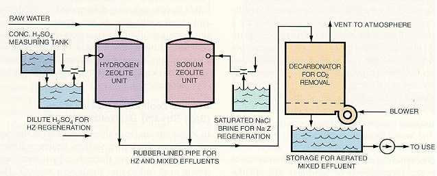
The desired level of blended water alkalinity can be maintained through control of the percentage of sodium zeolite and hydrogen zeolite water in the mixture. A higher percentage of sodium zeolite water results in higher alkalinity, and an increased percentage of hydrogen zeolite water reduces alkalinity.
In addition to reducing alkalinity, a split stream dealkalizer reduces the total dissolved solids of the water. This is important in high alkalinity waters, because the conductivity of these waters affects the process and can limit boiler cycles of concentration.
Sodium Zeolite/Chloride Anion Dealkalization
Strong base anion resin in the chloride form can be used to reduce the alkalinity of a water. Water flows through a zeolite softener and then an anion unit, which replaces the carbonate, bicarbonate, sulfate, and nitrate ions with chloride ions as shown in these reactions:
The chloride anion dealkalizer reduces alkalinity by approximately 90% but does not reduce total solids. When the resin nears exhaustion, treated water alkalinity increases rapidly, signaling the need for regeneration.
The zeolite softener is regenerated as previously described. In addition, the anion resin is also regenerated with a sodium chloride brine that returns the resin to the chloride form. Frequently, a small amount of caustic soda is added to the regenerant brine to enhance alkalinity removal.
Weak Acid Cation Dealkalization
Another method of dealkalization uses weak acid cation resins. Weak acid resins are similar in operation to strong acid cation resins, but only exchange for cations that are associated with alkalinity, as shown by these reactions:
where Z represents the resin. The carbonic acid (H2CO3) formed is removed by a decarbonator or degasser as in a split stream system.
The ideal influent for a weak acid cation system has a hardness level equal to the alkalinity (both expressed in ppm as CaCO3). In waters that are higher in alkalinity than hardness, the alkalinity is not removed to its lowest level. In waters containing more hardness than alkalinity, some hardness remains after treatment. Usually, these waters must be polished by a sodium zeolite softener to remove hardness.
During the initial portion of a weak acid cation service run (the first 40-60%) some cations associated with mineral anions exchange, producing small amounts of mineral acids in the effluent. As the service cycle progresses, alkalinity appears in the effluent. When the alkalinity in the effluent exceeds 10% of the influent alkalinity, the unit is removed from service and regenerated with a 0.5% sulfuric acid solution. The concentration of regenerant acid should be kept below 0.5-0.7%, to prevent calcium sulfate precipitation in the resin. Weak acid cation resin exchange is very efficient. Therefore, the amount of acid required is virtually equal (chemically) to the amount of cations removed during the service cycle.
If the materials of construction for the down-stream equipment or overall process cannot tolerate the mineral acidity present during the initial portions of the service cycle, a brine solution is passed through the regenerated weak acid resin prior to the final rinse. This solution removes the mineral acidity without a significant impact on the quality or length of the subsequent run.
Equipment used for a weak acid cation dealkalizer is similar to that used for a strong acid cation exchanger, with the exception of the resin. One variation of the standard design uses a layer of weak acid resin on top of strong acid cation resin. Because it is lighter, the weak acid resin remains on top. The layered resin system is regenerated with sulfuric acid and then with sodium chloride brine. The brine solution converts the strong acid resin to the sodium form. This resin then acts as a polishing softener.
Direct Acid Injection
In the process of direct acid injection and decarbonation, acid is used to convert alkalinity to carbonic acid. The carbonic acid dissociates to form carbon dioxide and water and the carbon dioxide is removed in a decarbonator. The use of an acid injection system should be approached with caution, because an acid overfeed or a breakdown in the pH control system can produce acidic feedwater, which corrodes the iron surfaces of feedwater systems and boilers. Proper pH monitoring and controlled caustic feed after decarbonation are required.
Advantages and Limitations of Dealkalization Systems
Ion exchange dealkalization systems produce hardness-free, low-alkalinity water at a reasonable cost, and with a high degree of reliability. They are well suited for processing feedwater for medium-pressure boilers, and for process water for the beverage industry. Split stream and weak acid cation systems also reduce the total dissolved solids. In addition to these advantages, the following disadvantages must be considered:
- dealkalizers do not remove all of the alkalinity and do not affect the silica content of a water
- dealkalizers require the same influent purity as other ion exchange processes; filtered water that is low in potential foulants must be used
- the water produced by a dealkalization system using a forced draft decarbonator becomes saturated with oxygen, so it is potentially corrosive
COUNTERFLOW AND MIXED BED DEIONIZATION
Due to increasing boiler operating pressures and the manufacture of products requiring contaminant-free water, there is a growing need for higher water quality than cation-anion demineralizers can produce. Therefore, it has become necessary to modify the standard demineralization process to increase the purity of the treated water. The most significant improvements in demineralized water purity have been produced by counterflow cation exchangers and mixed bed exchangers.
Counterflow Cation Exchangers
In a conventional demineralizer system, regenerant flow is in the same direction as the service flow, down through the resin bed. This scheme is known as co-current operation and is the basis for most ion exchange system designs. During the regeneration of a co-current unit, the contaminants are displaced through the resin bed during the regeneration. At the end of the regeneration, some ions, predominately sodium ions, remain in the bottom of the resin bed. Because the upper portion of the bed has been exposed to fresh regenerant, it is highly regenerated.
As the water flows through the resin during service, cations are exchanged in the upper portion of the bed first, and then move down through the resin as the bed becomes exhausted. Sodium ions that remained in the bed during regeneration diffuse into the decationized water before it leaves the vessel. This sodium leakage enters the anion unit where anion exchange produces caustic, raising the pH and conductivity of the demineralized water.
In a counterflow regenerated cation exchanger, the regenerant flows in the opposite direction of the service flow. For example, if the service flow is downward through the bed, the regenerant acid flow is up through the bed. As a result, the most highly regenerated resin is located where the service water leaves the vessel. The highly regenerated resin removes the low level of contaminants that have escaped removal in the top of the bed. This results in higher water purity than co-current designs can produce.
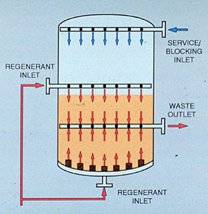
To maximize contact between the acid and resin and to keep the most highly regenerated resin from mixing with the rest of the bed, the resin bed must stay compressed during the regenerant introduction. This compression is usually achieved in one of two ways:
- a blocking flow of water or air is used
- the acid flow is split, and acid is introduced at both the top and the bottom of the resin bed (see Figure 8-11)
Mixed Bed Exchangers
A mixed bed exchanger has both cation and anion resin mixed together in a single vessel. As water flows through the resin bed, the ion exchange process is repeated many times, "polishing" the water to a very high purity. During regeneration, the resin is separated into distinct cation and anion fractions (see Figure 8-12).
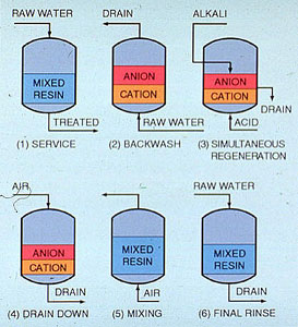
The resin is separated by backwashing, with the lighter anion resin settling on top of the cation resin. Regenerant acid is introduced through the bottom distributor, and caustic is introduced through distributors above the resin bed. The regenerant streams meet at the boundary between the cation and anion resin and discharge through a collector located at the resin interface. Following regenerant introduction and displacement rinse, air and water are used to mix the resins. Then the resins are rinsed, and the unit is ready for service.
Counterflow and mixed bed systems produce a purer water than conventional cation-anion demineralizers, but require more sophisticated equipment and have a higher initial cost. The more complicated regeneration sequences require closer operator attention than standard systems. This is especially true for a mixed bed unit.
OTHER DEMINERALIZATION PROCESSES
The standard cation-anion process has been modified in many systems to reduce the use of costly regenerants and the production of waste. Modifications include the use of decarbonators and degassers, weak acid and weak base resins, strong base anion caustic waste (to regenerate weak base anion exchangers), and reclamation of a portion of spent caustic for subsequent regeneration cycles. Several different approaches to demineralization using these processes (see Figure 8-13).

Decarbonators and Degassers
Decarbonators and degassers are economically beneficial to many demineralization systems, because they reduce the amount of caustic required for regeneration. Water from a cation exchanger is broken into small droplets by sprays and trays or packing in a decarbonator.
The water then flows through a stream of air flowing in the opposite direction. Carbonic acid present in the cation effluent dissociates into carbon dioxide and water. The carbon dioxide is stripped from the water by the air, reducing the load to the anion exchangers. Typical forced draft decarbonators are capable of removing carbon dioxide down to 10-15 ppm. However, water effluent from a decarbonator is saturated with oxygen.
In a vacuum degasser, water droplets are introduced into a packed column that is operated under a vacuum. Carbon dioxide is removed from the water due to its decreased partial pressure in a vacuum. A vacuum degasser usually reduces carbon dioxide to less than 2 ppm and also removes most of the oxygen from the water. However, vacuum degassers are more expensive to purchase and operate than forced draft decarbonators.
Weak Acid and Weak Base Resins
Weak functionality resins have a much higher regeneration efficiency than their strong function-ality counterparts. Weak acid cation resins, as described in the dealkalization section, exchange with cations associated with alkalinity. Weak base resins exchange with the mineral acid anions (SO4²¯, Cl¯, NO3¯) in a strong acid solution. The regeneration efficiency of weak resins is virtually stoichiometric, the removal of 1 kgr of ions (as CaCO3) requires only slightly more than 1 kgr of the regenerant ion (as CaCO3). Strong resins require three to four times the regenerant for the same contaminant removal.
Weak base resins are so efficient that it is common practice to regenerate a weak base exchanger with a portion of the "spent" caustic from regeneration of the strong base anion resin. The first fraction of the caustic from the strong base unit is sent to waste to prevent silica fouling of the weak base resin. The remaining caustic is used to regenerate the weak base resin.
An additional feature of weak base resins is their ability to hold natural organic materials that foul strong base resins and release them during the regeneration cycle. Due to this ability, weak base resins are commonly used to protect strong base resins from harmful organic fouling.
Regenerant Reuse
Due to the high cost of caustic soda and the increasing problems of waste disposal, many demineralization systems are now equipped with a caustic reclaim feature. The reclaim system uses a portion of the spent caustic from the previous regeneration at the beginning of the next regeneration cycle. The reused caustic is followed by fresh caustic to complete the regeneration. The new caustic is then reclaimed for use in the next regeneration. Typically, sulfuric acid is not reclaimed, because it is lower in cost and calcium sulfate precipitation is a potential problem.
CONDENSATE POLISHING
Ion exchange uses are not limited to process and boiler water makeup. Ion exchange can be used to purify, or polish, returned condensate, removing corrosion products that could cause harmful deposits in boilers.
Typically, the contaminants in the condensate system are particulate iron and copper. Low levels of other contaminants may enter the system through condenser and pump seal leaks or carry-over of boiler water into the steam. Condensate polishers filter out the particulates and remove soluble contaminants by ion exchange.
Most paper mill condensate polishers operate at temperatures approaching 200°F, precluding the use of anion resin. Cation resin, which is stable up to temperatures of over 270°F, is used for deep bed condensate polishing in these applications. The resin is regenerated with sodium chloride brine, as in a zeolite softener.
In situations where sodium leakage from the polisher adversely affects the boiler water internal chemical program or steam attemperating water purity, the resin can be regenerated with an ionized amine solution to prevent these problems.
The service flow rate for a deep bed polisher (20-50 gpm per square foot of resin surface area) is very high compared to that of a conventional softener. High flow rates are permissible because the level of soluble ions in the condensate can be usually very low. Particulate iron and copper are removed by filtration, while dissolved contaminants are reduced by exchange for the sodium or amine in the resin.
The deep bed cation resin condensate polisher is regenerated with 15 lb of sodium chloride per cubic foot of resin, in a manner similar to that used for conventional sodium zeolite regeneration. A solubilizing or reducing agent is often used to assist in the removal of iron. Sometimes, a supplemental backwash header is located just below the surface of the resin bed. This subsurface distributor, used prior to backwashing, introduces water to break up the crust that forms on the resin surface between regenerations.
An important consideration is the selection of a resin for condensate polishing. Because high pressure drops are generated by the high service flow rates and particulate loadings, and because many systems operate at high temperatures, considerable stress is imposed on the structure of the resin. A premium-grade gelular or macroreticular resin should be used in deep bed condensate polishing applications.
In systems requiring total dissolved solids and particulate removal, a mixed bed condensate polisher may be used. The temperature of the condensate should be below 140°F, which is the maximum continuous operating temperature for the anion resin. Additionally, the flow through the unit is generally reduced to approximately 20 gpm/ft².
Ion exchange resins are also used as part of a precoat filtration system (see Figure 8-14), for polishing condensate. The resin is crushed and mixed into a slurry, which is used to coat individual septums in a filter vessel. The powdered resin is a very fine filtering medium that traps particulate matter and removes some soluble contaminants by ion exchange. When the filter media becomes clogged, the precoat material is disposed of, and the septums are coated with a fresh slurry of powdered resin.
Veolia’s ion exchange products
COMMON ION EXCHANGE SYSTEM PROBLEMS
As in any dynamic operating system incorporating electrical and mechanical equipment and chemical operations, problems do occur in ion exchange systems. The problems usually result in poor effluent quality, decreased service run lengths, or increased consumption of regenerant. To keep the ion exchange system operating efficiently and reliably, changes in water quality, run lengths, or regenerant consumption should be considered whenever problems are detected.
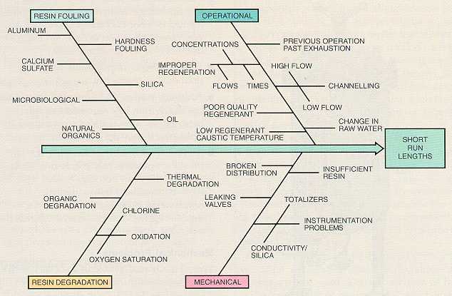
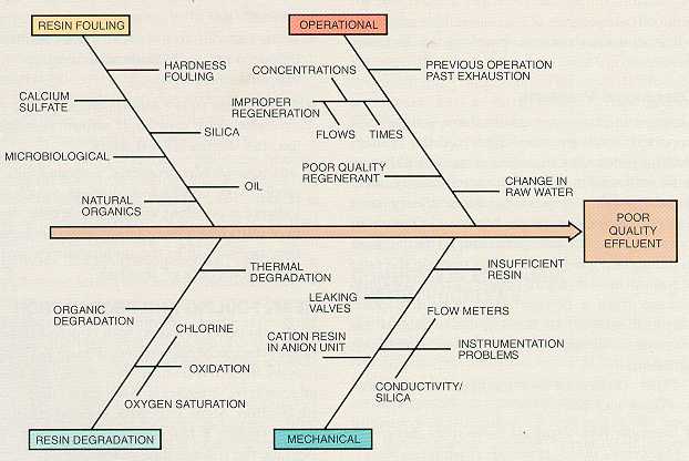
The cause-effect diagrams for short runs (see Figure 8-15) and poor-quality effluent (Figure 8-16) show that there are many possible causes for reduced performance of a demineralization system. Some of the more common problems are discussed below.
Operational Problems
Changes in raw water quality have a significant impact on both the run length and the effluent quality produced by an ion exchange unit. Although most well waters have a consistent quality, most surface water compositions vary widely over time. A 10% increase in the hardness of the water to a sodium zeolite softener causes a 10% decrease in the service run length. An increase in the ratio of sodium to total cations causes increased sodium leakage from a demineralizer system. Regular chemical analysis of the influent water to ion exchangers should be performed to reveal such variations.
Other causes of ion exchange operational problems include:
- Improper regenerations, caused by incorrect regenerant flows, times, or concentrations. Manufacturer's recommendations should be followed when regenerating ion exchange resins.
- Channeling, resulting from either high or low flow rates, increased suspended solids loading or poor backwashing. This causes premature exhaustion even when much of the bed is in a regenerated state.
- Resin fouling or degradation, caused by poor-quality regenerant.
- Failure to remove silica from the resin, which can result from low regenerant caustic temperature. This can lead to increased silica leakage and short service runs.
- Excess contaminants in the resin, due to previous operation past exhaustion loads. Because the resin becomes loaded with more contaminants than a normal regeneration is designed to remove, a double regeneration is required following an extended service run.
Mechanical Problems
Typical mechanical problems associated with ion exchange systems include:
- Leaking valves, which cause poor quality effluent and prolonged rinses.
- Broken or clogged distributor, which leads to channeling.
- Resin loss, due to excessive backwashing or failure in the underdrain screening or support media.
- Cation resin in the anion unit, causing extended rinse times and sodium leakage into the demineralized water.
- Instrumentation problems, such as faulty totalizers or conductivity meters, which may indicate a problem when none exists, or may introduce poor quality water to service. Instrumentation in the demineralizer area should be checked regularly.
RESIN FOULING AND DEGRADATION
Resin can become fouled with contaminants that hinder the exchange process. Figure 8-17 shows a resin fouled with iron.

The resin can also be attacked by chemicals that cause irreversible destruction. Some materials, such as natural organics (see Figure 8-18), foul resins at first and then degrade the resin as time passes.

This is the most common cause of fouling and degradation in ion exchange systems, and is discussed under "Organic Fouling," later in this chapter.
Causes of Resin Fouling
Iron and Manganese. Iron may exist in water as a ferrous or ferric inorganic salt or as a sequestered organic complex. Ferrous iron exchanges in resin, but ferric iron is insoluble and does not. Ferric iron coats cation resin, preventing exchange. An acid or a strong reducing agent must be used to remove this iron. Organically bound iron passes through a cation unit and fouls the anion resin. It must be removed along with the organic material. Manganese, present in some well waters, fouls a resin in the same manner as iron.
Aluminum. Aluminum is usually present as aluminum hydroxide, resulting from alum or sodium aluminate use in clarification or precipitation softening. Aluminum floc, if carried through filters, coats the resin in a sodium zeolite softener. It is removed by cleaning with either acid or caustic. Usually, aluminum is not a foulant in a demineralizer system, because it is removed from the resin during a normal regeneration.
Hardness Precipitates. Hardness precipitates carry through a filter from a precipitation softener or form after filtration by post-precipitation. These precipitates foul resins used for sodium zeolite softening. They are removed with acid.
Sulfate Precipitation. Calcium sulfate precipitation can occur in a strong acid cation unit operated in the hydrogen cycle. At the end of a service cycle, the top of the resin bed is rich in calcium. If sulfuric acid is used as the regenerant, and it is introduced at too high a concentration or too low a flow rate, precipitation of calcium sulfate occurs, fouling the resin. After calcium sulfate has formed, it is very difficult to redissolve; therefore, resin fouled by calcium sulfate is usually discarded. Mild cases of calcium sulfate fouling may be reversed with a prolonged soak in hydrochloric acid.
Barium sulfate is even less soluble than calcium sulfate. If a water source contains measurable amounts of barium, hydrochloric acid regeneration should be considered.
Oil Fouling. Oil coats resin, blocking the passage of ions to and from exchange sites. A surfactant can be used to remove oil. Care must be exercised to select a surfactant that does not foul resin. Oil-fouled anion resins should be cleaned with nonionic surfactants only.
Microbiological Fouling. Microbiological fouling can occur in resin beds, especially beds that are allowed to sit without service flow. Microbiological fouling can lead to severe plugging of the resin bed, and even mechanical damage due to an excessive pressure drop across the fouled resin. If microbiological fouling in standby units is a problem, a constant flow of recirculating water should be used to minimize the problem. Severe conditions may require the application of suitable sterilization agents and surfactants.
Silica Fouling. Silica fouling can occur in strong base anion resins if the regenerant temperature is too low, or in weak base resins if the effluent caustic from the SBA unit used to regenerate the weak base unit contains too much silica. At low pH levels, polymerization of the silica can occur in a weak base resin. It can also be a problem in an exhausted strong base anion resin. Silica fouling is removed by a prolonged soak in warm (120°F) caustic soda.
Causes of Irreversible Resin Degradation
Oxidation. Oxidizing agents, such as chlorine, degrade both cation and anion resins. Oxidants attack the divinylbenzene cross-links in a cation resin, reducing the overall strength of the resin bead. As the attack continues, the cation resin begins to lose its spherical shape and rigidity, causing it to compact during service. This compaction increases the pressure drop across the resin bed and leads to channeling, which reduces the effective capacity of the unit.
In the case of raw water chlorine, the anion resin is not directly affected, because the chlorine is consumed by the cation resin. However, downstream strong base anion resins are fouled by certain degradation products from oxidized cation resin.
If chlorine is present in raw water, it should be removed prior to ion exchange with activated carbon filtration or sodium sulfite. Approximately 1.8 ppm of sodium sulfite is required to consume 1 ppm of chlorine.
Oxygen-saturated water, such as that found following forced draft decarbonation, accelerates the destruction of strong base exchange sites that occurs naturally over time. It also accelerates degradation due to organic fouling.
Thermal Degradation. Thermal degradation occurs if the anion resin becomes overheated during the service or regeneration cycle. This is especially true for acrylic resins, which have temperature limitations as low as 100°F, and Type II strong base anion resins, which have a temperature limit of 105°F when in the hydroxide form.
Organic Fouling
Organic fouling is the most common and expensive form of resin fouling and degradation. Usually, only low levels of organic materials are found in well waters. However, surface waters can contain hundreds of parts per million of natural and man-made organic matter. Natural organics are derived from decaying vegetation. They are aromatic and acidic in nature, and can complex heavy metals, such as iron. These contaminants include tannins, tannic acid, humic acid, and fulvic acid.
Initially, organics block the strong base sites on a resin. This blockage causes long final rinses and reduces salt splitting capacity. As the foulant continues to remain on the resin, it begins to degrade the strong base sites, reducing the salt splitting capacity of the resin. The functionality of the site changes from strong base to weak base, and finally to a nonactive site.
Thus, a resin in the early stages of degradation exhibits high total capacity, but reduced salt splitting capacity. At this stage, cleaning of the resin can still return some, but not all, of the lost operating capacity. A loss in salt splitting capacity reduces the ability of the resin to remove silica and carbonic acid.
Organic fouling of anion resin is evidenced by the color of the effluent from the anion unit dur-ing regeneration, which ranges from tea-colored to dark brown. During operation, the treated water has higher conductivity and a lower pH.
Prevention. The following methods are used, either alone or in combination, to reduce organic fouling:
- Prechlorination and clarification. Water is prechlorinated at the source, and then clarified with an organic removal aid.
- Filtration through activated carbon. It should be noted that a carbon filter has a finite capacity for removal of organic material and that the removal performance of the carbon should be monitored frequently.
- Macroporous and weak base resin ahead of strong base resin. The weak base or macroporous resin absorbs the organic material and is eluted during regeneration.
- Specialty resins. Acrylic and other specialty resins that are less susceptible to organic fouling have been developed.
Inspection and Cleaning. In addition to these preventive procedures, a program of regular inspection and cleaning of the ion exchange system helps to preserve the life of anion resin. Most cleaning procedures use one of the following:
- Warm (120°F) brine and caustic. Mild oxidants or solubilizing agents can be added to improve the cleaning.
- Hydrochloric acid. When resins are also fouled with significant amounts of iron, hydrochloric acids are used.
- Solutions of 0.25-0.5% sodium hypochlorite. This procedure destroys the organic material but also significantly degrades the resin. Hypochlorite cleaning is considered a last resort.
It is important to clean an organically fouled resin before excessive permanent degradation of the strong base sites occurs. Cleaning after permanent degradation has occurred removes significant amounts of organic material but does not improve unit performance. The condition of the resin should be closely monitored to identify the optimum schedule for cleaning.
RESIN TESTING AND ANALYSIS
To track the condition of ion exchange resin and determine the best time for cleaning it, the resin should be periodically sampled and analyzed for physical stability, foulant levels, and the ability to perform the required ion exchange.
Samples should be representative of the entire resin bed. Therefore, samples should be collected at different levels within the bed, or a grain thief or hollow pipe should be used to obtain a "core" sample. During sampling, the inlet and regenerant distributor should be examined, and the condition of the top of the resin bed should be noted. Excessive hills or valleys in the resin bed are an indication of flow distribution problems.
The resin sample should be examined microscopically for signs of fouling and cracked or broken beads.It should also be tested for physical properties, such as density and moisture content (see Figure 8-19).

The level of organic and inorganic foulants in the resin should be determined and compared to known standards and the previous condition of the resin. Finally, the salt splitting and total capacity should be measured on anion resin samples to evaluate the rate of degradation or organic fouling.
Contact Veolia experts to find a ion exchange solution for your business
Figure 8-1. Microscopic view of cellular resin beads (20-50 mesh) of a sulfonated styrene-divinylbenzene strong acid cation exhcanger. (Courtesy of Rohm and Haas Company.)
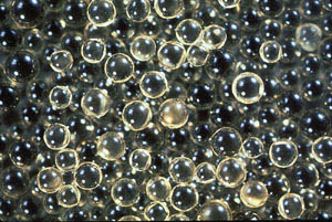
Figure 8-2. Microscopic view of a macroporous strong base anion resin. (Courtesy of Dow Chemical Company.)
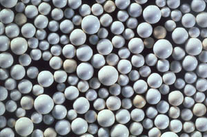
Figure 8-3. Chemical structural formula of sulfonic strong acid cation resin (Amberlite IR-120), (XL): cross link; (PC): polymer chain; (ES): exchange site; (EI): exchangeable ion.
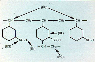
Figure 8-4. Schematic of hydrated strong acid cation exchanger. (Courtesy of Rohm and Haas Company.)
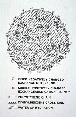
Figure 8-5. Typical sodium zeolite softener effluent profile.

Figure 8-6. Sodium zeolite softener. (Courtesy of Graver Water Division, Ecodyne Corporation.)
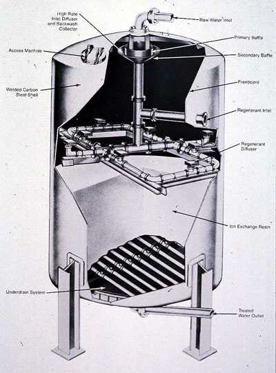
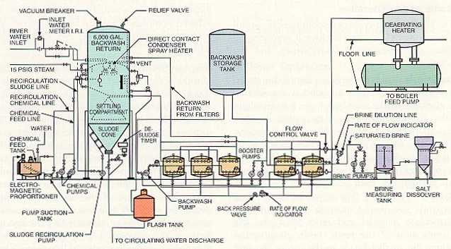
Figure 8-7. Combined hot lime/hot zeolite softening system. (Courtesy of Water Conditioning Division, Envirex, Inc.)

Figure 8-8. Typical effluent profile for strong acid cation exchanger.
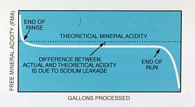
Figure 8-9. Conductivity/silica profile for strong base anionn exchanger.

Figure 8-10. Sodium zeolite/hydrogen zeolite split stream softener.

Figure 8-11. Counterflow cation profile showing dual acid flow blocking method.

Figure 8-12. Significant steps in the regeneration sequence for a mixed bed exchanger.

Figure 8-13. Demineralizer systems.
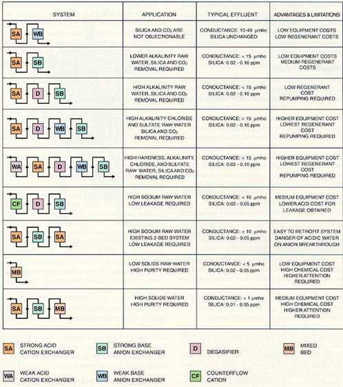
Figure 8-14. Powdered resin condensate polisher. (Courtesy of Graver Water Div., Ecodyne Corporation).

Figure 8-15. Cause-effect diagram for short runs in a two-bed demineralizer system.

Figure 8-16. Cause-effect diagram for poor effluent quality in a two-bed demineralizer system.

Figure 8-17. Iron fouled resin.
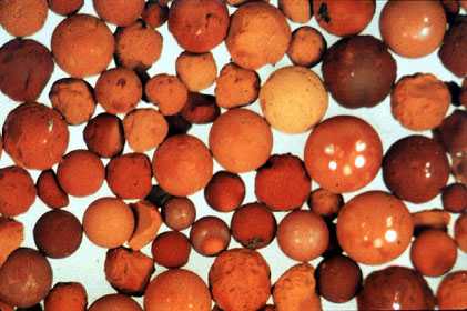
Figure 8-18. Anion resin fouled with organic material.
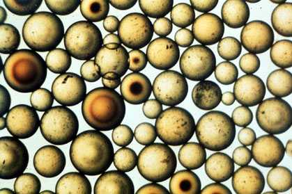
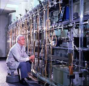
Figure 8-19. Periodic sampling and evaluation of the resin is required to keep performance and efficiency at optimum levels.