- Chemistry of precipitation softening
- Cold lime softening
- Warm lime softening
- Hot process softening
- Silica reduction
- Alkalinity reduction
- Reduction of other contaminants
- Precipitation process (chemical) control
- Equipment employed
- Limitations
Precipitation softening processes are used to reduce raw water hardness, alkalinity, silica, and other constituents. This helps prepare water for direct use as cooling tower makeup or as a first-stage treatment followed by ion exchange for boiler makeup or process use. The water is treated with lime or a combination of lime and soda ash (carbonate ion). These chemicals react with the hardness and natural alkalinity in the water to form insoluble compounds. The compounds precipitate and are removed from the water by sedimentation and, usually, filtration. Waters with moderate to high hardness and alkalinity concentrations (150-500 ppm as CaCO3) are often treated in this fashion.
Chemistry of Precipitation Softening
In almost every raw water supply, hardness is present as calcium and magnesium bicarbonate, often referred to as carbonate hardness or temporary hardness. These compounds result from the action of acidic, carbon dioxide laden rain water on naturally occurring minerals in the earth, such as limestone. For example:
| CO2 | + | H2O | = | H2CO3 |
| carbon dioxide | water | carbonic acid |
| H2CO3 | + | CaCO3 ¯ | = | Ca(HCO3)2 |
| carbonic acid | calcium carbonate | calcium bicarbonate |
Hardness may also be present as a sulfate or chloride salt, referred to as noncarbonate or permanent hardness. These salts are caused by mineral acids present in rain water or the solution of naturally occurring acidic minerals.
The significance of "carbonate" or "temporary" hardness as contrasted to "noncarbonate" or "permanent" hardness is that the former may be reduced in concentration simply by heating. In effect, heating reverses the solution reaction:
| Ca(HCO3)2 | + | Heat | = | CaCO3 ¯ | + | H2O | + | CO2 |
| calcium bicarbonate | calcium carbonate | water | carbon dioxide |
Reduction of noncarbonate hardness, by contrast, requires chemical addition. A combination of lime and soda ash, along with coagulant and flocculant chemicals, is added to raw water to promote a precipitation reaction. This allows softening to take place.
Precipitation softening accomplished at ambient temperatures is referred to as cold lime softening. When hydrated lime, Ca(OH)2, is added to the water being treated, the following reactions occur:
| CO2 | + | Ca(OH)2 | = | CaCO3 ¯ | + | H2O |
| carbon dioxide | calcium hydroxide | calcium carbonate | water |
| Ca(HCO3)2 | + | Ca(OH)2 | = | 2CaCO3 ¯ | + | 2H2O |
| calcium bicarbonate | calcium hydroxide | calcium carbonate | water |
| Mg(HCO3)2 | + | 2Ca(OH)2 | = | Mg(OH)2 ¯ | + | 2CaCO3 ¯ | + | 2H2O |
| magnesium bicarbonate | calcium hydroxide | magnesium hydroxide | calcium carbonate | water |
If the proper chemical control is maintained on lime feed, the calcium hardness may be reduced to 35-50 ppm. Magnesium reduction is a function of the amount of hydroxyl (OH-) alkalinity excess maintained. Figures 7-1 and 7-2 show these relationships.
Noncarbonate or permanent calcium hardness, if present, is not affected by treatment with lime alone. If noncarbonate magnesium hardness is present in an amount greater than 70 ppm and an excess hydroxyl alkalinity of about 5 ppm is maintained, the magnesium will be reduced to about 70 ppm, but the calcium will increase in proportion to the magnesium reduction.
For example, in cold lime treatment of a water containing 110 ppm of calcium, 95 ppm of magnesium, and at least 110 ppm of alkalinity (all expressed as calcium carbonate), calcium could theoretically be reduced to 35 ppm and the magnesium to about 70 ppm. However, an additional 25 ppm of calcium would be expected in the treated water due to the following reactions:
| MgSO4 | + | Ca(OH)2 | = | Mg(OH)2 ¯ | + | CaSO4 |
| magnesium sulfate | calcium hydroxide | magnesium hydroxide | calcium sulfate |
| MgCl2 | + | Ca(OH)2 | = | Mg(OH)2 ¯ | + | CaCl2 |
| magnesium chloride | calcium | magnesium hydroxide | calcium chloride |
To improve magnesium reduction, which also improves silica reduction in cold process softening, sodium aluminate may be used. The sodium aluminate provides hydroxyl ion (OH-) needed for improved magnesium reduction, without increasing calcium hardness in the treated water. In addition, the hydrolysis of sodium aluminate results in the formation of aluminum hydroxide, which aids in floc formation, sludge blanket conditioning, and silica reduction. The reactions are as follows:
| Na2Al2O4 | + | 4H2O | = | 2Al(OH)3 ¯ | + | 2NaOH |
| sodium aluminate | water | aluminum hydroxide | sodium hydroxide |
| Mg | [ |
|
] | + | 2NaOH | = | Mg(OH)2¯ | + | [ | Na2SO4 |
] |
|
Cl2 |
2NaCl | ||||||||||
| magnesium | sulfate/ chloride | sodium hydroxide | magnesium hydroxide | sodium sulfate/ chloride |
Soda ash (Na2CO3) may be used to improve hardness reduction. It reacts with noncarbonate calcium hardness according to the following:
| CaSO4 | + | Na2CO3 | = | CaCO3 ¯ | + | Na2SO4 |
| calcium sulfate | sodium carbonate | calcium carbonate | sodium sulfate |
| CaCl2 | + | Na2CO3 | = | CaCO3 ¯ | + | 2NaCl |
| calcium chloride | sodium carbonate | calcium carbonate | sodium chloride |
However, noncarbonate magnesium hardness reduction in cold process softening requires added lime. The reactions are as follows:
| MgSO4 | + | Ca(OH)2 | + | Na2CO3 | = | Mg(OH)2 ¯ | + | CaCO3 ¯ | + | Na2SO4 |
| magnesium sulfate | calcium hydroxide | sodium carbonate | magnesium hydroxide | calcium carbonate | sodium sulfate |
| MgCl2 | + | Ca(OH)2 | + | Na2CO3 | = | Mg(OH)2¯ | + | CaCO3 ¯ | + | 2NaCl |
| magnesium chloride | calcium hydroxide | sodium carbonate | magnesium hydroxide | calcium carbonate | sodium chloride |
In these reactions, dissolved solids are not reduced because a solution reaction product (sodium sulfate or sodium chloride) is formed.
The warm lime softening process operates in the temperature range of 120-140°F (49-60°C). The solubilities of calcium, magnesium, and silica are reduced by increased temperature. Therefore, they are more effectively removed by warm lime softening than by cold lime softening. This process is used for the following purposes:
- To recover waste heat as an energy conservation measure. The water to be treated is heated by a waste stream, such as boiler blowdown or low-pressure exhaust steam, to recover the heat content.
- To prepare feed to a demineralization system. The lower levels of calcium, magnesium, and especially silica reduce the ionic loading on the demineralizer when warm lime-softened water is used rather than cold lime-softened water. This may reduce both the capital and operating costs of the demineralizer. However, most strong base anion resins have a temperature limitation of 140°F (60°C); therefore, additional increases in temperature are not acceptable for increasing the effectiveness of contaminant reduction.
- To lower the blowdown discharge from cooling systems. Cooling tower blowdown may be treated with lime and soda ash or caustic to reduce calcium and magnesium levels so that much of the blowdown may be returned to the cooling system. Silica levels in the recirculating cooling water are also controlled in this manner.
In any warm lime or warm lime-soda ash process, temperature control is critical because temperature variations of as little as 4°F/hr (2°C/hr) can cause gross carryover of the softener pricipitates.
Hot process softening is usually carried out under pressure at temperatures of 227-240°F (108-116°C). At the operating temperature, hot process softening reactions go essentially to completion. This treatment method involves the same reactions described above, except that raw water CO2 is vented and does not participate in the lime reaction. The use of lime and soda ash permits hardness reduction down to 0.5 gr/gal, or about 8 ppm, as calcium carbonate.
Magnesium is reduced to 2-5 ppm because of the lower solubility of magnesium hydroxide at the elevated temperatures.
Hot process softening can also provide very good silica reduction. The silica reduction is accomplished through adsorption of the silica on the magnesium hydroxide precipitate. If there is insufficient magnesium present in the raw water to reduce silica to the desired level, magnesium compounds (such as magnesium oxide, magnesium sulfate, magnesium carbonate, or dolomitic lime) may be used. Figure 7-3 is a plot of magnesium oxide vs. raw water silica (in ppm), which may be used to estimate the quantity of magnesium oxide required to reduce silica to the levels indicated . Magnesium oxide is the preferred chemical because it does not increase the dissolved solids concentration of the water.
Good sludge contact enhances silica reduction. To ensure optimum contact, sludge is frequently recirculated back to the inlet of the unit.
Cold or warm process softening is not as effective as hot process softening for silica reduction. However, added magnesium oxide and good sludge contact will improve results.
Predicted analyses of a typical raw water treated by various lime and lime-soda softening processes are presented in Table 7-1.
| Table 7-1. Typical softener effluent analyses. | |||||
| Raw Water | Removal of Calcium Alkalinity Cold-Lime | Lime-soda Softening (Cold) | Lime-soda Softening (Hot) | Lime Softening (Hot) | |
| Total Hardness (as CaCO3), ppm | 250 | 145 | 81 | 20 | 120 |
| Calcium Hardness (as CaCO3), ppm | 150 | 85 | 35 | 15 | 115 |
| Magnesium Hardness (as CaCO3), ppm | 100 | 60 | 46 | 5 | 5 |
| "P" Alkalinity (as CaCO3), ppm | 0 | 27 | 37 | 23 | 18 |
| "M" Alkalinity (as CaCO3), ppm | 150 | 44 | 55 | 40 | 28 |
| Silica (as SiO2), ppm | 20 | 19 | 18 | 1-2 | 1-2 |
| pH | 7.5 | 10.3 | 10.6 | 10.5 | 10.4 |
Treatment by lime precipitation reduces alkalinity. However, if the raw water alkalinity exceeds the total hardness, sodium bicarbonate alkalinity is present. In such cases, it is usually necessary to reduce treated water alkalinity in order to reduce condensate system corrosion or permit increased cycles of concentration.
Treatment by lime converts the sodium bicarbonate in the raw water to sodium carbonate as follows:
| 2NaHCO3 | + | Ca(OH)2 | = | CaCO3 ¯ | + | Na2CO3 | + | 2H2O |
| sodium bicarbonate | calcium hydroxide | calcium carbonate | sodium carbonate | water |
Calcium sulfate (gypsum) may be added to reduce the carbonate to required levels. The reaction is as follows:
| Na2CO3 | + | CaSO4 | = | CaCO3 ¯ | + | Na2SO4 |
| sodium carbonate | calcium sulfate | calcium carbonate | sodiumsulfate |
This is the same reaction involved in the reduction of noncarbonate calcium hardness previously discussed. Table 7-2 shows the treated water alkalinity relationships to be expected in lime-soda ash softened water.
| Table 7-2. Alkalinity relationships as determined by titrations. | |||
| Hydroxide | Carobnate | Bicarbonate | |
| P = O | O | O | M |
| P = M | P | O | O |
| 2P = M | O | 2P | O |
| 2P < M | O | 2P | M - 2P |
| 2P > M | 2P - M | 2(M - P) | M - 2P |
Reduction of Other Contaminants
Lime softening processes, with the usual filters, will reduce oxidized iron and manganese to about 0.05 and 0.01 ppm, respectively. Raw water organics (color-contributing colloids) are also reduced.
Turbidity, present in most surface supplies, is reduced to about 1.0 NTU with filtration following chemical treatment. Raw water turbidity in excess of 100 NTU may be tolerated in these systems; however, it may be necessary to coagulate raw water solids with a cationic polymer before the water enters the softener vessel to assist liquid-solids separation.
Oil may also be removed by adsorption on the precipitates formed during treatment. However, oil in concentrations above about 30 ppm should be reduced before lime treatment because higher concentrations of oil may exert a dispersing influence and cause floc carryover.
Precipitation Process (Chemical) Control
Lime or lime-soda softener control is usually based on treated water alkalinity and hardness. Samples are tested to determine the alkalinity to the P (phenolphthalein, pH 8.3) and M (methyl orange or methyl purple, pH 4.3) end points. The following relationships apply:
| P (ppm as CaCO3) | = | OH- | + | ½ CO32- |
| hydroxyl | carbonate |
| M (ppm CaCO3) | = | OH- | + | CO32- | + | HCO3- |
| hydroxyl | carbonate | bicarbonate |
In the presence of hydroxyl ion (OH-), bicarbonate concentration is so low that it may be assumed to be zero.
In the precipitation process, it is advisable to ensure that all of the bicarbonate has been converted to carbonate (the least soluble form of the calcium); therefore, a slight excess of hydroxyl ion should be maintained in the treated water. When the equations above are combined, it can be shown that when 2P - M is positive, hydroxyl ion is present. The usual control range is:
2P – M = 5-15 ppm
This corresponds to a pH of approximately 10.2.
If soda ash is also used, the control is on the excess carbonate ion. As shown in Figure 7-1 (above), excess carbonate will depress the calcium to the level desired. The usual control range for hot lime-soda units is:
M (alkalinity) - TH (total hardness) = 20-40 ppm
For cold lime-soda softening, where effluent magnesium hardness is significantly greater than in hot lime or soda, the control range above may be inappropriate. For cold lime—soda units, soda ash can be controlled such that:
2(M - P) - Calcium hardness = 20-40 ppm
Care must be exercised in the specification of soda ash control ranges. If the softened water is to be used as boiler feedwater, hardness removal by the addition of soda ash may not be worth the cost of the resulting increase in steam condensate system corrosion. This corrosion is caused by the higher levels of carbon dioxide in the steam resulting from the higher carbonate alkalinity of the feedwater.
Coagulants/Flocculants/Sludge Conditioners
Organic polymer flocculants and coagulants are preferred over inorganic salts of aluminum or iron. Polymers add minimal dissolved solids to the water and their use results in reduced sludge quantity compared to the use of inorganic coagulants. Inorganic coagulants must react with raw water alkalinity to form the metallic precipitate that aids in clarification and sludge bed conditioning. For example, alum reacts as follows:
| 3Ca(HCO3)2 | + | Al2(SO4)3 | = | 3CaSO4 | + | 2Al(OH)3 ¯ | + | 6CO2 |
| calcium bicarbonate | aluminum sulfate | calciumsulfate | aluminum hydroxide | carbon dioxide |
The precipitated aluminum hydroxide is incorporated within the sludge produced by the softening reactions. This increases the fluidity of the softener sludge, which allows for increased solids contact, improving softening and effluent clarity.
Waters producing high calcium-to-magnesium precipitation ratios usually need sludge bed conditioning chemical feed for proper operation. Specialized organic polymers are available for proper conditioning of the sludge bed without the use of inorganic salts.
Four potentially adverse effects of using inorganic salts may be noted:
- The inorganic salt reduces the alkalinity. This converts the hardness to noncarbonate hardness, which is not affected by lime. As a result, inorganic salts increase hardness in water that is naturally deficient in bicarbonate alkalinity.
- When the water is to be treated further by ion exchange, regenerant consumption is increased.This is due to the higher hardness and the added soluble sulfate/chloride load.
- The carbon dioxide generated by the reaction has a lime demand which is twice that of the bicarbonate. Therefore, increased chemical addition is required.
- Soluble aluminum in the softener effluent interferes with softened water alkalinity titrations, even when very low levels of soluble aluminum exist. This interference, which necessitates an increase in lime feed, causes falsely low (2P - M) readings and may be partly responsible for the additional removal of magnesium seen when aluminum salts are used.
Equipment Employed Cold Process
The first cold lime-soda softening was carried out in "batch" fashion. An excess of treating chemicals was mixed with the water in a large basin. After approximately 4 hr, the treated water was decanted from the basin, leaving the settled precipitates in the basin.
Today, continuous sludge-contact softeners (see Figures 7-4 and 7-5 ) are used to provide a constant flow with effluent quality superior to that obtained through batch treatment. Treating chemicals are added as a function of flow rate and water quality to the rapid mix zone of the unit. Sludge, recirculated either internally or externally to the unit, may be returned to this rapid mix zone for improved softening, softened water clarity, and silica reduction.
The water then flows to the slow mix zone of the unit. Here, the precipitation reactions continue and the precipitates formed become large enough to begin settling. In the sludge-contact unit, the water flows through a bed of sludge for additional contact. The sludge level is maintained by the proper combination of sludge bed conditioning chemicals, mechanical agitation, hydraulic suspension, and sludge blowdown. A discernible line of separation between clarified water and slurry pool should exist in a properly operated unit. Effluent turbidity is usually less than 10 NTU.
Flow rate is usually limited to less than 1.5 gpm/ft2 of settling area. A retention time of 1 hr is required to allow the softening reactions to come as close to completion as possible.
Because the reactions in cold process softening are not complete, the water contaminant levels leaving the unit are unstable. With additional time and/or increased temperature, further precipitation will occur downstream of the unit. Frequently, acid or carbon dioxide is added to stabilize the water. The pH is reduced from about 10.2 to between 8.0 and 9.0, which converts
the carbonate to the more soluble bicarbonate. Ionically, the reaction is:
| H+ | + | CO32- | = | HCO3- |
| hydrogen ion | carbonateion | bicarbonate ion |
A typical cold lime softener system is shown in Figure 7-6 .
Hot Process
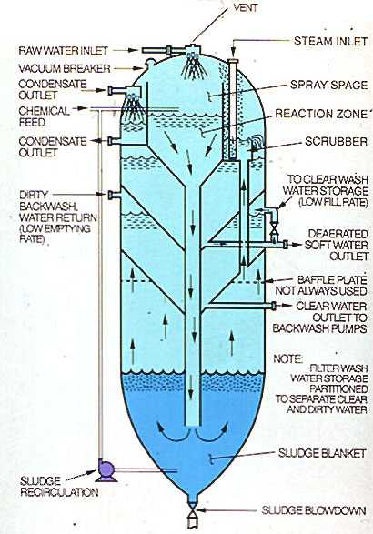
Two hot process softener designs are illustrated in Figures 7-7 and 7-8 . The former, the simplest in design and fabrication, is referred to as a "downflow" unit. The latter, which incorporates additional features, is referred to as an "upflow" unit. Many variations in design of both units exist, but the principle of operation is quite similar.
In each unit, water is admitted to the top of the vessel designed to operate at 5-15 psig saturated steam pressure (227-240°F, 108-116°C). An inlet valve is used to control the inlet water flow as a function of the operating level of the vessel. The water is sprayed into the steam space of the unit and is heated to within 2 or 3 degrees of the saturation temperature of the steam. Heating reduces the noncondensible gas content of the water. Oxygen and carbon dioxide are released and vented to the atmosphere with a controlled loss of heating steam. Although they are not deaerators, hot process units reduce oxygen to about 0.3 ppm (0.21 cm³/L) and carbon dioxide to 0.
This residual oxygen level in the high-temperature water is aggressive and will attack downstream equipment such as filters and zeolites. Therefore, users should consider feeding a chemical oxygen scavenger to the effluent of hot process softeners.
Treatment chemicals are introduced into the top of the vessel as a function of flow and raw water analysis. Although the reactions go essentially to completion quite rapidly, a minimum of 1 hr of retention is designed into the unit. Also, flow rate through the unit is limited to 1.7-2.0 gpm/ft². Filter backwash water may be withdrawn from the outlet of the unit, from the filtered water header, or from internal or external storage. Internal storage compartments are illustrated in Figure 7-8. Filter backwash water is usually returned to the unit for recovery.
In the downflow design, the water leaves the vessel after reversing direction and enters the internal hood. Precipitates separate from the water at the hood and continue downward into the cone for removal by blowdown. Sludge blowdown is proportioned to raw water flow. For improved silica reduction, sludge is recirculated from the cone back to the top of the unit.
For optimum silica reduction, a sludge-contact unit (shown in Figure 7-8) is used. Water and chemicals enter the top of the unit and flow to the bottom of the softener through a downcomer. The sludge level is maintained in such a way that the downcomer always discharges into the sludge bed. This ensures good contact with the sludge, which is rich in magnesium hydroxide. Also, the sludge bed acts as a filter, entrapping finer solids before the water exits near the top of the vessel. Sludge recycle may also be used.
The upflow design also lends itself to easier incorporation of internal compartments for filter backwash storage and return, and condensate or treated water deaeration.
Given proper consideration of raw water quality and ultimate end use of the treated water, the application of precipitation processes has few limitations. However, operational difficulties may be encountered unless the following factors are controlled:
- Temperature. Cold and warm units are subject to carryover if the temperature varies more than 4°F/hr (2°C/hr). Hot process units are less sensitive to slight temperature variations. However, a clogged or improper spray pattern can prevent proper heating of the water, and carryover can result.
- Hydraulics. In any system, steady-state operation within design limits optimizes the performance of the equipment. Rapid flow variations can cause severe system upsets. Suitable treated water storage capacity should be incorporated into the total system design to minimize load swings on the softener.
- Chemical Control. This should be as precise as possible to prevent poor water quality. Because of the comparatively constant quality of most well waters, changes in chemical feed rates are largely a function of flow only. However, surface water quality may vary hourly. Therefore, for proper control, it is imperative that users perform frequent testing of the raw water as well as the treated effluent, and adjust chemical feed accordingly.
Figure 7-1. Calcium reduction vs. carbonate alkalinity.
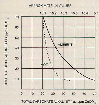
Figure 7-2. Magnesium reduction vs. causticity.
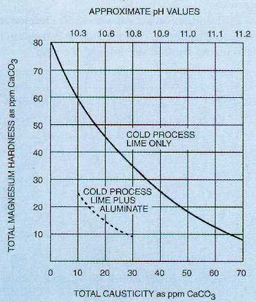
Figure 7-3. Approximate magnesium oxide requirements for silica removal in a hot process softener.
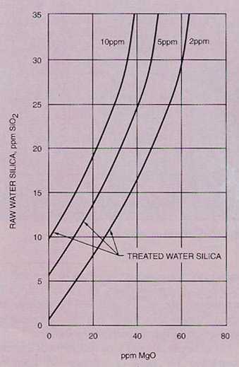
Figure 7-4. Sludge-contact softener. (Courtesy of Graver Water Division, Ecodyne Corporation.)
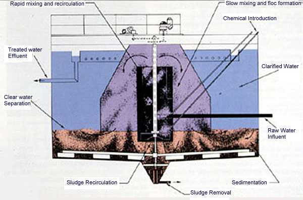
Figure 7-5. Sludge-contact softener. (Courtesy of the Permutit Company, Inc.)
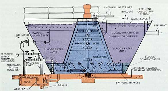
Figure 7-6. Typical precipitator with associated gravity filters.
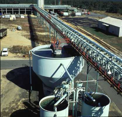
Figure 7-7. Downflow design of hot process softener.
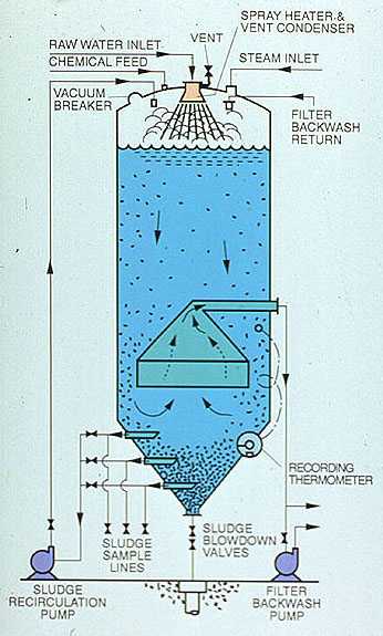
Figure 7-8. Sludge contact hot process softener