- Typical construction
- Types of Media
- Mixed media filter beds
- Capping of sand filters
- Gravity filters
- Pressure filters
- Upflow filters
- Automatic gravity filters
- Continuous cleaning filters
- Filter washing-Gravity filters
- In-line clarification
- Precoat filtration
Filtration is used in addition to regular coagulation and sedimentation for removal of solids from surface water or wastewater. This prepares the water for use as potable, boiler, or cooling make-up. Wastewater filtration helps users meet more stringent effluent discharge permit requirements.
Filtration, usually considered a simple mechanical process, actually involves the mechanisms of adsorption (physical and chemical), straining, sedimentation, interception, diffusion, and inertial compaction.
Filtration does not remove dissolved solids, but may be used together with a softening process, which does reduce the concentration of dissolved solids. For example, anthracite filtration is used to remove residual precipitated hardness salts remaining after clarification in precipitation softening.
In most water clarification or softening processes where coagulation and precipitation occur, at least a portion of the clarified water is filtered. Clarifier effluents of 2-10 NTU may be improved to 0.1-1.0 NTU by conventional sand filtration. Filtration ensures acceptable suspended solids concentrations in the finished water even when upsets occur in the clarification processes.
Conventional gravity and pressure rapid filters operate downflow. The filter medium is usually a 15-30 in. deep bed of sand or anthracite. Single or multiple grades of sand or anthracite may be used.
A large particle bed supports the filter media to prevent fine sand or anthracite from escaping into the underdrain system. The support bed also serves to distribute backwash water. Typical support beds consist of 1 8-1 in. gravel or anthracite in graded layers to a depth of 12-16 in.
Quartz sand, silica sand, anthracite coal, garnet, magnetite, and other materials may be used as filtration media. Silica sand and anthracite are the most commonly used types. When silica is not suitable (e.g., in filters following a hot process softener where the treated water is intended for boiler feed), anthracite is usually used.
The size and shape of the filter media affect the efficiency of the solids removal. Sharp, angular media form large voids and remove less fine material than rounded media of equivalent size. The media must be coarse enough to allow solids to penetrate the bed for 2-4 in. Although most suspended solids are trapped at the surface or in the first 1-2 in. of bed depth, some penetration is essential to prevent a rapid increase in pressure drop.
Sand and anthracite for filters are rated by effective particle size and uniformity. The effective size is such that approximately 10% of the total grains by weight are smaller and 90% are larger. Therefore, the effective size is the minimum size of most of the particles. Uniformity is measured by comparison of effective size to the size at which 60% of the grains by weight are smaller and 40% are larger. This latter size, divided by the effective size, is called the uniformity coefficient-the smaller the uniformity coefficient, the more uniform the media particle sizes.
Finer sands result in shallower zones for the retention of suspended matter. The most desirable media size depends on the suspended solids characteristics as well as the effluent quality requirements and the specific filter design. In general, rapid sand filters use sand with an effective size of 0.35-0.60 mm (0.014-0.024 in.) and a maximum uniformity coefficient of 1.7. Coarse media, often 0.6-1.0 mm (0.024-0.04 in.), are used for closely controlled coagulation and sedimentation.
The terms "multilayer," "in-depth," and "mixed media" apply to a type of filter bed which is graded by size and density. Coarse, less dense particles are at the top of the filter bed, and fine, more dense particles are at the bottom. Downflow filtration allows deep, uniform penetration by particulate matter and permits high filtration rates and long service runs. Because small particles at the bottom are also more dense (less space between particles), they remain at the bottom. Even after high-rate backwashing, the layers remain in their proper location in the mixed media filter bed.
Table 6-1 lists four media that are used in multilayer filtration. Several other mixed media combinations have also been tested and used effectively. The use of too many different media layers can cause severe backwashing difficulties. For example, if all four materials listed in Table 6-1 were used in the same filter, a wash rate high enough to expand the magnetite layer might wash the anthracite from the filter. High wash water requirements would also result.
| Table 6-1. Media used in multilayer filtration. | ||
| Media | Effective size, mm (in.) | Specific gravity |
| Anthracite | 0.7-1.7 (0.03-0.07) | 1.4 |
| Sand | 0.3-0.7 (0.01-0.03) | 2.6 |
| Garnet | 0.4-0.6 (0.016-0.024) | 3.8 |
| Magnetite | 0.3-0.5 (0.01-0.02) | 4.9 |
Anthracite/sand filter beds normally provide all of the advantages of single-media filtration but require less backwash water than sand or anthracite alone. Similar claims have been made for anthracite/sand/garnet mixed units. The major advantages of dual-media filtration are higher rates and longer runs. Anthracite/sand/garnet beds have operated at normal rates of approximately 5 gpm/ft² and peak rates as high as 8 gpm/ft² without loss of effluent quality.
Rapid sand filters can be converted for mixed media operation to increase capacity by 100%. The cost of this conversion is much lower than that of installing additional rapid sand filters.
Capping involves the replacement of a portion of the sand with anthracite. In this conversion, a 2-6 in. layer of 0.4-0.6 mm (0.016-0.024 in.) sand is removed from the surface of a bed and replaced with 4-8 in. of 0.9 mm (0.035 in.) anthracite. If an increase in capacity is desired, a larger amount of sand is replaced. Pilot tests should be run to ensure that a reduction in the depth of the finer sand does not reduce the quality of the effluent.
Gravity filters (see Figure 6-1) are open vessels that depend on system gravity head for operation. Apart from the filter media, the essential components of a gravity filter include the following:
- The filter shell, which is either concrete or steel and can be square, rectangular, or circular. Rectangular reinforced concrete units are most widely used.
- The support bed, which prevents loss of fine sand or anthracite through the underdrain system. The support bed, usually 1-2 ft deep, also distributes backwash water.
- An underdrain system, which ensures uniform collection of filtered water and uniform distribution of backwash water. The system may consist of a header and laterals, with perforations or strainers spaced suitably. False tank bottoms with appropriately spaced strainers are also used for underdrain systems.
- Wash water troughs, large enough to collect backwash water without flooding. The troughs are spaced so that the horizontal travel of backwash water does not exceed 3-3 ft. In conventional sand bed units, wash troughs are placed approximately 2 ft above the filter surface. Sufficient freeboard must be provided to prevent loss of a portion of the filter media during operation at maximum backwash rates.
- Control devices that maximize filter operation efficiency. Flow rate controllers, operated by venturi tubes in the effluent line, automatically maintain uniform delivery of filtered water. Backwash flow rate controllers are also used. Flow rate and head loss gauges are essential for efficient operation.
Pressure filters are typically used with hot process softeners to permit high-temperature operation and to prevent heat loss. The use of pressure filters eliminates the need for repumping of filtered water. Pressure filters are similar to gravity filters in that they include filter media, supporting bed, underdrain system, and control device; however, the filter shell has no wash water troughs.
Pressure filters, designed vertically or horizon-tally, have cylindrical steel shells and dished heads. Vertical pressure filters (see Figure 6-2) range in diameter from 1 to 10 ft with capacities as great as 300 gpm at filtration rates of 3 gpm/ft². Horizontal pressure filters, usually 8 ft in diameter, are 10-25 ft long with capacities from 200 to 600 gpm. These filters are separated into compartments to allow individual backwashing. Backwash water may be returned to the clarifier or softener for recovery.
Pressure filters are usually operated at a service flow rate of 3 gpm/ft². Dual or multimedia filters are designed for 6-8 gpm/ft². At ambient temperature, the recommended filter backwash rate is 6-8 gpm/ft² for anthracite and 13-15 gpm/ft² for sand. Anthracite filters associated with hot process softeners require a backwash rate of 12-15 gpm/ft² because the water is less dense at elevated operating temperatures. Cold water should not be used to backwash a hot process filter. This would cause expansion and contraction of the system metallurgy, which would lead to metal fatigue. Also, the oxygen-laden cold water would accelerate corrosion.
Upflow units contain a single filter medium–usually graded sand. The finest sand is at the top of the bed with the coarsest sand below. Gravel is retained by grids in a fixed position at the bottom of the unit. The function of the gravel is to ensure proper water distribution during the service cycle. Another grid above the graded sand prevents fluidization of the media. Air injection during cleaning (not considered backwash because the direction of flow is the same as when in-service) assists in the removal of solids and the reclassification of the filter media. During operation, the larger, coarse solids are removed at the bottom of the bed, while smaller solids particles are allowed to penetrate further into the media. Typical service flow rates are 5-10 gpm/ft². An example of this unit is shown in Figure 6-3.
Several manufacturers have developed gravity filters that are backwashed automatically at a preset head loss. Head loss (water level above the media) actuates a backwash siphon and draws wash water from storage up through the bed and out through the siphon pipe to waste. A low level in the backwash storage section breaks the siphon, and the filter returns to service.
Automatic gravity filters are available in diameters of up to 15 ft. When equipped with a high-rate, multilayer media, a single large-diameter unit can filter as much as 1,000 gpm. An example is shown in Figure 6-4.
Continuous cleaning filter systems eliminate off-line backwash periods by backwashing sections of the filter or portions of the filter media continuously, on-line. Various designs have been introduced. An example is shown in Figure 6-5.
FILTER WASHING-GRAVITY FILTERS
Periodic washing of filters is necessary for the removal of accumulated solids. Inadequate cleaning permits the formation of permanent clumps, gradually decreasing filter capacity. If fouling is severe, the media must be cleaned chemically or replaced.
For cleaning of rapid downflow filters, clean water is forced back up and through the media. In conventional gravity units, the backwash water lifts solids from the bed into wash troughs and carries them to waste. Either of two backwash techniques can be used, depending on the design of the media support structure and the accessory equipment available:
- High-rate backwash, which expands the media by at least 10%. Backwash rates of 12-15 gpm/ft² or higher are common for sand, and rates for anthracite may range from 8 to 12 gpm/ft².
- Low-rate backwash, with no visible bed expansion, combined with air scouring.
Where only water is used for backwash, the backwash may be preceded by surface washing. In surface washing, strong jets of high-pressure water from fixed or revolving nozzles assist in breaking the filter surface crust. After the surface wash (when there is provision for surface washing), the unit is backwashed for approximately 5-10 min. Following backwash, a small amount of rinse water is filtered to waste, and the filter is returned to service.
High-rate backwash can cause the formation of mud balls inside the filter bed. A high backwash rate and resulting bed expansion can produce random currents in which certain zones of the expanded bed move upward or downward. Encrusted solids from the surface can be carried down to form mud balls. Efficient surface washing helps prevent this condition.
Air scouring with low-rate backwashing can break up the surface crust without producing random currents, if the underdrain system is de-signed to distribute air uniformly. Solids removed from the media collect in the layer of water between the media surface and wash channels. After the air is stopped, this dirty water is nor-mally flushed out by increased backwash water flow rate or by surface draining. Wash water consumption is approximately the same whether water-only or air/water backwashing is employed.
In-line clarification is the removal of suspended solids through the addition of in-line coagulant followed by rapid filtration. This process is also referred to as in-line filtration, or contact filtration. The process removes suspended solids without the use of sedimentation basins. Coagulation may be achieved in in-line clarification by either of two methods:
- an inorganic aluminum or iron salt used alone or with a high molecular weight polymeric coagulant
- a strongly cationic organic polyelectrolyte
Because metal hydroxides form precipitates, only dual-media filters should be used with inorganic coagulant programs. Floc particles must be handled in filters with coarse-to-fine graded media to prevent rapid blinding of the filter and eliminate backwashing difficulties. Where a high molecular weight polymeric coagulant is used, feed rates of less than 0.1 ppm maximize solids removal by increasing floc size and promoting particle absorption within the filter. This filtration technique readily yields effluent turbidities of less than 0.5 NTU. Figure 6-6.
The second method of coagulant pretreatment involves the use of a single chemical, a strongly charged cationic polyelectrolyte. This treatment forms no precipitation floc particles, and usually no floc formation is visible in the filter influent. Solids are removed within the bed by adsorption and by flocculation of colloidal matter directly onto the surface of the sand or anthracite media. The process may be visualized as seeding of the filter bed surfaces with positive cationic charges to produce a strong pull on the negatively charged particles. Because gelatinous hydroxide precipitates are not present in this process, single- media or upflow filters are suitable for poly-electrolyte clarification.
In-line clarification provides an excellent way to improve the efficiency of solids removal from turbid surface waters. Effluent turbidity levels of less than 1 NTU are common with this method.
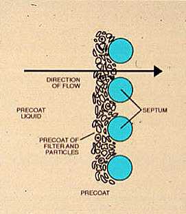
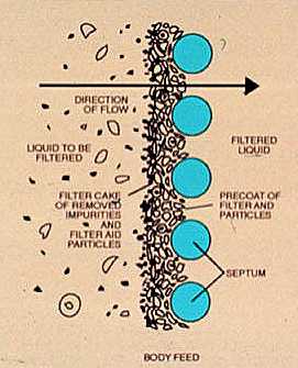
Precoat filtration is used to remove very small particulate matter, oil particles, and even bacteria from water. This method is practical only for relatively small quantities of water which contain low concentrations of contaminants.
Precoat filtration may be used following conventional clarification processes to produce water of very low suspended solids content for specific application requirements. For example, precoat filters are often used to remove oil from contaminated condensate.
In precoat filtration, the precoat media, typically diatomaceous earth, acts as the filter media and forms a cake on a permeable base or septum. The base must prevent passage of the precoat media without restricting the flow of filtered water and must be capable of withstanding high pressure differentials. Filter cloths, porous stone tubes, porous paper, wire screens, and wire-wound tubes are used as base materials.
The supporting base material is first precoated with a slurry of precoat media. Additional slurry (body feed) is usually added during the filter run. When the accumulation of matter removed by filtration generates a high pressure drop across the filter, the filter coating is sloughed off by backwashing. The filter bed is then precoated and returned to service. Chemical coagulants are not usually needed but have been used where an ultrapure effluent is required.
Figure 6-1. Typical gravity filter unit. (Courtesy Roberts Filter Manufacturing Co.)
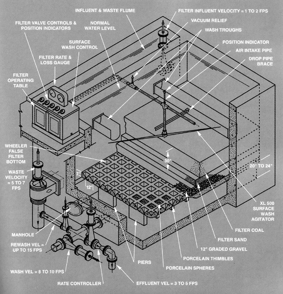
Figure 6-2. Vertical-type pressure sand filter. (Courtesy the Permutit Company, Inc.)
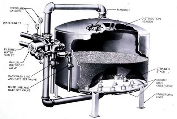
Figure 6-3. Upflow in-line filter. (Courtesy of L'Eau Claire Systems, Inc.)
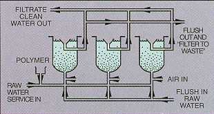
Figure 6-4. Monovalve gravity filter. (Courtesy of Graver Div., Ecodyne Corporation.)
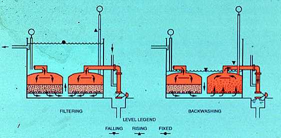
Figure 6-5. DynaSand continuous cleaning filter. (Courtesy of Parkson Corp.)
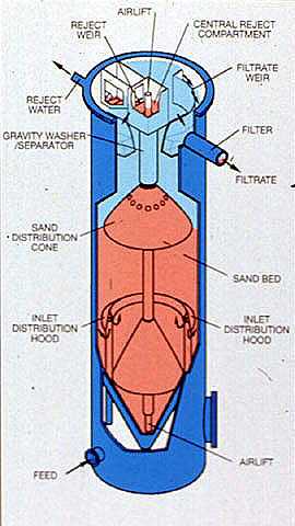
Figure 6-6. Principles of diatomite filtration. (Courtesy of Johns-Manville Corp.)