
- Cooling towers
- Cycles of Concentration, Water Balance
- Deposition Control
- Corrosion Control Programs
- Future Considerations
- Monitoring and Control of Cooling Water Equipment
An open recirculating cooling system uses the same water repeatedly to cool process equipment. Heat absorbed from the process must be dissipated to allow reuse of the water. Cooling towers, spray ponds, and evaporative condensers are used for this purpose.
Open recirculating cooling systems save a tremendous amount of fresh water compared to the alternative method, once-through cooling. The quantity of water discharged to waste is greatly reduced in the open recirculating method, and chemical treatment is more economical. However, open recirculating cooling systems are inherently subject to more treatment-related problems than once-through systems:
- cooling by evaporation increases the dissolved solids concentration in the water, raising corrosion and deposition tendencies
- the relatively higher temperatures significantly increase corrosion potential
- the longer retention time and warmer water in an open recirculating system increase the tendency for biological growth
- airborne gases such as sulfur dioxide, ammonia or hydrogen sulfide can be absorbed from the air, causing higher corrosion rates
- microorganisms, nutrients, and potential foulants can also be absorbed into the water across the tower
Cooling towers are the most common method used to dissipate heat in open recirculating cooling systems. They are designed to provide intimate air/water contact. Heat rejection is primarily by evaporation of part of the cooling water. Some sensible heat loss (direct cooling of the water by the air) also occurs, but it is only a minor portion of the total heat rejection.
Types of Towers
Cooling towers are classified by the type of draft (natural or mechanical) and the direction of airflow (crossflow or counterflow). Mechanical draft towers are further subdivided into forced or induced draft towers.
Natural draft towers. Sometimes called "hyperbolic" towers due to the distinctive shape and function of their chimneys, natural draft towers do not require fans. They are designed to take advantage of the density difference between the air entering the tower and the warmer air inside the tower. The warm, moist air inside the tower has a lower density, so it rises as denser, cool air is drawn in at the base of the tower. The tall (up to 500 ft) chimney is necessary to induce adequate airflow. Natural draft towers can be either counterflow or crossflow designs. The tower pictured is a crossflow model. The fill is external to the shell forming a ring around the base. In a counterflow model, the fill is inside the shell. In both models, the empty chimney accounts for most of the tower height.
Mechanical Draft Towers. Mechanical draft towers use fans to move air through the tower. In a forced draft design, fans push air into the bottom of the tower. Almost all forced draft towers are counterflow designs. Induced draft towers have a fan at the top to draw air through the tower. These towers can use either crossflow or counterflow air currents and tend to be larger than forced draft towers.
Counterflow Towers. In counterflow towers, air moves upward, directly opposed to the downward flow of water. This design provides good heat exchange because the coolest air contacts the coolest water. Headers and spray nozzles are usually used to distribute the water in counterflow towers.
Crossflow Towers. In crossflow towers, air flows horizontally across the downward flow of water. The crossflow design provides an easier path for the air, thus increasing the airflow for a given fan horsepower. Crossflow towers usually have a gravity feed system-a distribution deck with evenly spaced metering orifices to distribute the water. Often, the deck is covered to retard algae growth.
Fill Section. The fill section is the most important part of the tower. Packing or fill of various types is used to keep the water distributed evenly and to increase the water surface area for more efficient evaporation. Originally, fill consisted of "splash bars" made of redwood or pressure-treated fir. Splash bars are now available in plastic as well. Other types of fill include plastic splash grid, ceramic brick, and film fill.
Film fill has became very popular in recent years. It consists of closely packed, corrugated, vertical sheets, which cause the water to flow down through the tower in a very thin film. Film fill is typically made of plastic. Polyvinyl chloride (PVC) is commonly used for systems with a maximum water temperature of 130°F or less. Chlorinated PVC (CPVC) can withstand temperatures to approximately 165°F.
Film fill provides more cooling capacity in a given space than splash fill. Splash fill can be partially or totally replaced with film fill to in-crease the capacity of an existing cooling tower. Because of the very close spacing, film fill is very susceptible to various types of deposition. Calcium carbonate scaling and fouling with suspended solids has occurred in some systems. Process contaminants, such as oil and grease, can be direct foulants and/or lead to heavy biological growth on the fill. Any type of deposition can severely reduce the cooling efficiency of the tower.
Louvers. Louvers. Louvers are used to help direct airflow into the tower and minimize the amount of windage loss (water being splashed or blown out the sides of the tower).
Drift Eliminators. Drift Eliminators. "Drift" is a term used to describe droplets of water entrained in the air leaving the top of the tower. Because drift has the same composition as the circulating water, it should not be confused with evaporation. Drift should be minimized because it wastes water and can cause staining on buildings and autos at some distance from the tower. Drift eliminators abruptly change the direction of airflow, imparting centrifugal force to separate water from the air. Early drift eliminators were made of redwood in a herringbone structure. Modern drift eliminators are typically made of plastic and come in many different shapes. They are more effective in removing drift than the early wood versions, yet cause less pressure drop.
Approach to Wet Bulb, Cooling Range
Cooling towers are designed to cool water to a certain temperature under a given set of condi-tions. The "wet bulb temperature" is the lowest temperature to which water can be cooled by evaporation. It is not practical to design a tower to cool to the wet bulb temperature. The difference between the cold sump temperature and the wet bulb temperature is called the "approach." Towers are typically designed with a 7-15°F approach. The temperature difference between the hot return water and the cold sump water is referred to as the "cooling range" (DT ). Cooling range is usually around 10-25°F but can be as high as 40°F in some systems.
CYCLES OF CONCENTRATION, WATER BALANCE
Calculation of Cycles of Concentration
Water circulates through the process exchangers and over the cooling tower at a rate referred to as the "recirculation rate." Water is lost from the system through evaporation and blowdown. For calculation purposes, blowdown is defined as all nonevaporative water losses (windage, drift, leaks, and intentional blowdown).
Makeup is added to the system to replace evaporation and blowdown.
Approximately 1000 Btu of heat is lost from the water for every pound of water evaporated. This is equal to evaporation of about 1% of the cooling water for each 10°F temperature drop across the cooling tower. The following equation describes this relationship between evaporation, recirculation rate, and temperature change:
![]()
where: E = evaporation, gpm RR = recirculation rate, gpm
DT = cooling range, °F F = evaporation factor
The evaporation factor, F, equals 1 when all cooling comes from evaporation. For simplicity, this is often assumed to be the case. In reality, F varies with relative humidity and dry bulb temperature. The actual F value for a system is generally between 0.75 and 1.0, but can be as low as 0.6 in very cold weather.
As pure water is evaporated, minerals are left behind in the circulating water, making it more concentrated than the makeup water. Note that blowdown has the same chemical composition as circulating water. "Cycles of concentration" (or "cycles") are a comparison of the dissolved solids level of the blowdown with the makeup water. At 3 cycles of concentration, blowdown has three times the solids concentration of the makeup.
Cycles can be calculated by comparison of the concentrations of a soluble component in the makeup and blowdown streams. Because chloride and sulfate are soluble even at very high concentrations, they are good choices for measurement. However, the calculation results could be invalid if either chlorine or sulfuric acid is fed to the system as part of a water treatment program.
Cycles based on conductivity are often used as an easy way to automate blowdown. However, cycles based on conductivity can be slightly higher than cycles based on individual species, due to the addition of chlorine, sulfuric acid, and treatment chemicals.
Using any appropriate component: 
Cycles of concentration can also be expressed as follows: ![]()
where: MU = makeup (evaporation + blowdown), gpm BD = blowdown, gpm
Note that the relationship based on flow rate in gallons per minute is the inverse of the concentration relationship.
If E + BD is substituted for MU : 
where:
E = evaporation Solving for blowdown, this equation becomes: 
This is a very useful equation in cooling water treatment. After the cycles of concentration have been determined based on makeup and blowdown concentrations, the actual blowdown being lost from the system, or the blowdown required to maintain the system at the desired number of cycles, can be calculated.
Because treatment chemicals are not lost through evaporation, only treatment chemicals lost through blowdown (all nonevaporative water loss) must be replaced. Thus, calculation of blowdown is critical in determining treatment feed rates and costs.
Factors Limiting Cycles of Concentration
Physical Limitations. There is a limit to the number of cycles attainable in a cooling tower. Windage, drift, and leakage are all sources of unintentional blowdown. Drift losses of up to 0.2% of the recirculation rate in older towers can limit cycles to 5-10. Additional losses due to leaks and windage can further limit some older systems. New towers often carry drift guarantees of 0.02% of recirculation rate or less. Newly constructed systems that use towers with highly efficient drift eliminators and have no extraneous losses may be mechanically capable of achieving 50-100 cycles or more.
Chemical Limitations. As a water's dissolved solids level increases, corrosion and deposition tendencies increase. Because corrosion is an electrochemical reaction, higher conductivity due to higher dissolved solids increases the corrosion rate (see Chapter 24 for further discussion). It becomes progressively more difficult and expensive to inhibit corrosion as the specific conductance approaches and exceeds 10,000 µmho.
Some salts have inverse temperature solubility; i.e., they are less soluble at higher temperature and thus tend to form deposits on hot exchanger tubes. Many salts also are less soluble at higher pH. As cooling tower water is concentrated and pH increases, the tendency to pre-cipitate scale-forming salts increases.
Because it is one of the least soluble salts, calcium carbonate is a common scale former in open recirculating cooling systems. Calcium and magnesium silicate, calcium sulfate, and other types of scale can also occur. In the absence treatment there is a wide range in the relative solubility of calcium carbonate and gypsum, the form of calcium sulfate normally found in cooling systems.
Calcium carbonate scaling can be predicted qualitatively by the Langelier Saturation Index (LSI) and Ryznar Stability Index (RSI). The indices are determined as follows:
Langelier Saturation Index = pHa - pHs Ryznar Stability Index = 2(pHs) - pHa
The value pHs (pH of saturation) is a function of total solids, temperature, calcium, and alkalinity. pHa is the actual pH of the water.
A positive LSI indicates a tendency for calcium carbonate to deposit. The Ryznar Stability Index shows the same tendency when a value of 6.0 or less is calculated. A more complete discussion of LSI and RSI is presented in Chapter 25, Deposit and Scale Control-Cooling Systems.
With or without chemical treatment of the cooling water, cycles of concentration are eventually limited by an inability to prevent scale formation.
As noted earlier, there are many contaminants in cooling water that contribute to deposit problems. Three major types of deposition are discussed here: scaling, general fouling, and biological fouling.
Scale Formation
Scale formation in a cooling system can be controlled by:
- minimizing cycles of concentration through blowdown control
- adding acid to prevent deposition of pH-sensitive species
- softening the water to reduce calcium
- using scale inhibitors to allow operation under supersaturated conditions
Blowdown Control. Increasing blowdown to limit cycles of concentration is an effective way to reduce the scaling potential of circulating water. However, high rates of blowdown are not always tolerable and, depending on water quality, cannot always provide complete scale control. In many localities, supplies of fresh water are limited and costly.
Table 31-1. Makeup and blowdown rates at various cycles
Table 31-1. Makeup and blowdown rates at various cycles a
| Cycles | Makeup, gpm | Blowdown, gpm |
| 2 | 2000 | 1000 |
| 4 | 1330 | 333 |
| 8 | 1140 | 143 |
| 15 | 1070 | 71 |
| 20 | 1050 | 53 |
a RR = 50,000 gpm; DT = 20 °F.
The CO2 formed is vented across the cooling tower, while sulfate remains as a by-product.
Lowering pH through acid feed also reduces the scaling tendencies of other pH-sensitive species such as magnesium silicate, zinc hydroxide, and calcium phosphate.
Because control of acid feed is critical, an automated feed system should be used. Overfeed of acid contributes to excessive corrosion; loss of acid feed can lead to rapid scale formation. An acid dilution system should be used for proper mixing to prevent acid attack of the concrete sump.
When makeup water sulfate is high and/or the tower is operated at high cycles, sulfuric acid feed can lead to calcium sulfate scaling. Sometimes, hydrochloric acid is used instead of sulfuric acid in such cases. However, this can result in high chloride levels, which often contribute significantly to increased corrosion rates-especially pitting and/or stress cracking of stainless steel.
Injection of carbon dioxide into the circulating water to control pH has been proposed occasionally. Such treatment reduces pH but does not reduce alkalinity. The circulating water is aerated each time it passes over the cooling tower. This reduces the carbon dioxide concentration in the water to the equilibrium value for the atmospheric conditions, causing the pH to rise. The rapid increase in pH across the tower can lead to calcium carbonate scaling on the tower fill. Because of aeration, carbon dioxide does not cycle and must be fed based on system recirculation rate. It is generally not considered a practical means of controlling pH in open recirculating systems.
Water Softening. Water Softening. Lime softening of the makeup or a sidestream can be used to lower the calcium and, often, alkalinity. This reduces both the calcium carbonate and calcium sulfate scaling tendencies of the water at a given number of cycles and pH level. Sidestream lime softening is also used to lower silica levels.
Scale Inhibitors. Scale Inhibitors. Cooling systems can be operated at higher cycles of concentration and/or higher pH when appropriate scale inhibitors are applied. These materials interfere with crystal growth, permitting operation at "supersaturated" conditions. Organic phosphates, also called phosphonates, are commonly used to inhibit calcium carbonate scale. Phosphonates or various polymeric materials can be used to inhibit other types of scale, such as calcium sulfate and calcium phosphate.
There is a relatively high-quality makeup water at various cycles of concentration. With no chemical additives of any type, this water is limited to 2 cycles. At 5 cycles the pH is approximately 8.3, and the LSI is +1.5. The system can be operated without acid feed if a scale inhibitor is used. At 10 cycles with no acid feed, the LSI is +2.5 and the water is treatable with a calcium carbonate scale inhibitor. At 15 cycles and no acid feed, the theoretical pH is 9.2 and the LSI is +3.2. In this case, the water cannot be treated effectively at 15 cycles with conventional calcium carbonate inhibitors. Acid should be fed to reduce the pH to 8.7 or below so that a scale inhibitor may be used.
Table 31-2. Recirculating cooling water at various cycles.
| Circulating Water at 2 cycles |
Circulating Water at 5 cycles |
Circulating Water at 10 cycles | Circulating Water at 15 cycles | |||
| Makeup Water | No Acid Feed | No Acid Feed | No Acid Feed | No Acid Feed | Acid for pH 8.7 | |
| Calcium (as CaCO3), ppm |
50 | 100 | 250 | 500 | 750 | 750 |
| Magnesium (as CaCO3), ppm |
20 | 40 | 100 | 300 | 300 | 300 |
| M Alkalinity (as CaCO3), ppm |
40 | 80 | 200 | 400 | 600 | 310 |
| Sulfate (as SO4-2), ppm |
40 | 80 | 200 | 400 | 600 | 890 |
| Chloride (as Cl- | 10 | 20 | 50 | 100 | 150 | 150 |
| Silica (as SiO2), ppm | 10 | 20 | 50 | 100 | 150 | 150 |
| pH | 7.0 | 7.6 | 8.3 | 8.9 | 9.2 | 8.7 |
| pHs (120 °F) | 8.2 | 7.6 | 6.8 | 6.4 | 6.0 | 6.2 |
| LSI | -1.2 | 0 | +1.5 | +2.5 | +3.2 | +2.5 |
| RSI | 9.4 | 7.6 | 5.3 | 3.9 | 2.8 | 3.7 |
| CaCO3 Controlled by a: | B | B/S | B/S | X | B/A/S | |
a B, blowdown only; B/S, blowdown plus scale inhibitor; B/A/S, blowdown plus aid plus CaCO3scale inhibitor; X, cannot operate.
General Fouling Control
Species that do not form scale (iron, mud, silt, and other debris) can also cause deposition problems. Because these materials are composed of solid particles, their deposition is often more flow-related than heat-related. Suspended solids tend to drop out in low-flow areas, such as the tower sump and heat exchangers with cooling water on the shell side. In addition to serving as a water reservoir, the tower sump provides a settling basin. The accumulated solids can be removed from the sump periodically by vacuum or shoveling methods. Natural and synthetic polymers of various types can be used to minimize fouling in heat exchangers.
Organic process contaminants, such as oil and grease, can enter a system through exchanger leaks. Surfactants can be used to mitigate the effects of these materials. Fouling is addressed in further detail in Chapter 25.
Biological Fouling Control
An open recirculating cooling system provides a favorable environment for biological growth. If this growth is not controlled, severe biological fouling and accelerated corrosion can occur. Corrosion inhibitors and deposit control agents cannot function effectively in the presence of biological accumulations.
A complete discussion of microorganisms and control of biological fouling can be found in Chapter 26. Oxidizing antimicrobials (e.g., chlorine and halogen donors) are discussed in Chapter 27.
The addition of a single corrosion inhibitor, such as phosphate or zinc, is not sufficient for effec-tive treatment of an open recirculating cooling system. A comprehensive treatment program that addresses corrosion and all types of deposition is required. All corrosion inhibitor programs require a good biological control program and, in some cases, supplemental deposit control agents for specific foulants.
Chromate-Based Programs
For many years, programs based on chromate provided excellent corrosion protection for cooling systems. However, it was soon recognized that chromate, as a heavy metal, had certain health and environmental hazards associated with it. Treatments employing chromate alone at 200-500 ppm rapidly gave way to programs such as "Zinc Dianodic," which incorporated zinc and phosphate to reduce chromate levels to 15-25 ppm.
Federal regulations limiting discharge of chromate to receiving streams sparked further efforts to reduce or eliminate chromate. The most recent concern relating to chromate treatment involves chromate present in cooling tower drift. When inhaled, hexavalent chrome is a suspected carcinogen. Therefore, as of May 1990, the use of chromate in comfort cooling towers was banned by the EPA. It is expected that chromate use in open recirculating cooling systems will be banned altogether by the end of 1993.
Copper Corrosion Inhibitors
Chromate is a good corrosion inhibitor for copper as well as steel. Therefore, no specific copper corrosion inhibitor was needed in most chromate-based programs. However, most other mild steel inhibitors do not effectively protect copper alloys. Therefore, nonchromate programs generally include a specific copper corrosion inhibitor when copper alloys are present in the system.
Early Phosphate/Phosphonate Programs
Many early corrosion treatment programs used polyphosphate at relatively high levels. In water, polyphosphate undergoes a process of hydrolysis, commonly called "reversion," which returns it to its orthophosphate state. In early programs, this process often resulted in calcium orthophosphate deposition.
Later improvements used combinations of ortho-, poly-, and organic phosphates. The general treatment ranges are as follows:
| Orthophosphate | 2-10 ppm |
| Polyphosphate | 2-10 ppm |
| Phosphonate | 2-10 ppm |
| pH | 6.5-8.5 |
A more specific set of control limits within these ranges was developed, based on individual water characteristics and system operating conditions. Where low-calcium waters were used (i.e., less than 75 ppm), zinc was often added to provide the desired corrosion protection.
With close control of phosphate levels, pH, and cycles, it was possible to achieve satisfactory cor-rosion protection with minimal deposition. However, there was little room for error, and calcium phosphate deposition was frequently a problem.
Dianodic II ®
The Dianodic II ® concept revolutionized non-chromate treatment technology with its introduction in 1979. This program uses relatively high levels of orthophosphate to promote a protective oxide film on mild steel surfaces, providing superior corrosion inhibition. The use of high phosphate levels was made possible by the development of superior acrylate-based copolymers. These polymers are capable of keeping high levels of orthophosphate in solution under typical cooling water conditions, eliminating the problem of calcium phosphate deposition encountered with previous programs.
The general control ranges for Dianodic II are as follows:
| Total inorganic phosphate | 10-25 ppm |
| Calcium (as CaCO3) | 75-1200 ppm |
| pH | 6.8-7.8 |
ore detailed control ranges are developed for individual systems, based on water characteristics and system operating conditions.
Dianodic II programs have been successfully protecting cooling systems since their introduction. Continuing research has yielded many improvements in this treatment approach, including newer, more effective polymers, which have expanded the applicability to more diverse water chemistries. The most widely used treatment program, Dianodic II, is an industry standard in nonchromate treatment.
Alkaline Treatment Programs
There are several advantages to operating a cooling system in an alkaline pH range of 8.0-9.2. First, the water is inherently less corrosive than at lower pH. Second, feed of sulfuric acid can be minimized or even eliminated, depending on the makeup water chemistry and desired cycles. A system using this makeup could run an alkaline treatment program in the 4-10 cycle range with no acid feed. This eliminates the high cost of properly maintaining an acid feed system, along with the safety hazards and handling problems associated with acid.
Even if acid cannot be eliminated, there is still an advantage to alkaline operation. A pH of 8.0-9.0 corresponds to an alkalinity range more than twice that of pH 7.0-8.0. Therefore, pH is more easily controlled at higher pH, and the higher alkalinity provides more buffering capacity in the event of acid overfeed.
A disadvantage of alkaline operation is the increased potential to form calcium carbonate and other calcium- and magnesium-based scales. This can limit cycles of concentration and necessitate the use of deposit control agents.
Alkaline Zinc Programs. One of the most effective alkaline programs relies on a combination of zinc and organic phosphate (phosphonate) for corrosion inhibition. Zinc is an excellent cathodic inhibitor that allows operation at lower calcium and alkalinity levels than other alkaline treatments. However, discharge of cooling tower blowdown containing zinc may be severely limited due to its aquatic toxicity. Zinc-based programs are most applicable in plants where zinc can be removed in the waste treatment process.
Alkaline Phosphate Programs. Combinations of organic and inorganic phosphates are also used to inhibit corrosion at alkaline pH. Superior synthetic polymer technology has been applied to eliminate many of the fouling problems encountered with early phosphate/phosphonate programs. Because of the higher pH and alkalinity, the required phosphate levels are lower than in Dianodic II treatments. General treatment ranges are as follows:
- Inorganic phosphate 2-10 ppm
- Organic phosphate 3-8 ppm
- Calcium (as CaCO3) 75-1200 ppm
- pH 8.0-9.2
All-Organic Programs
All-organic programs use no inorganic phosphates or zinc. Corrosion protection is provided by phosphonates and organic film-forming inhibitors. These programs typically require a pH range of 8.7-9.2 to take advantage of calcium carbonate as a cathodic inhibitor.
Molybdate-Based Programs
In order to be effective, molybdate alone requires very high treatment concentrations. Therefore, it is usually applied at lower levels (e.g., 2-20 ppm) and combined with other inhibitors, such as inorganic and organic phosphates. Many investigators believe that molybdate, at the levels mentioned above, is effective in controlling pitting on mild steel. Because molybdate is more expensive than most conventional corrosion inhibitors on a parts per million basis, the benefit of molybdate addition must be weighed against the incremental cost. Use of molybdate may be most appropriate where phosphate and/or zinc discharge is limited.
The chemical influence of cooling system blowdown on receiving streams is being closely scrutinized in the United States, where the cleanup of waterways is a high priority. Zinc and phosphate effluent limitations are in place in many states. Extensive research to develop new, more "environmentally friendly" treatment programs is underway and likely to continue. Extensive testing to determine toxicity and environmental impact of new molecules will be required. The answers are not simple, and the new programs are likely to be more expensive than current technology.
MONITORING AND CONTROL OF COOLING WATER TREATMENT
There are many factors that contribute to corrosion and fouling in cooling water systems. The choice and application of proper treatment chemicals is only a small part of the solution. Sophisticated monitoring programs are needed to identify potential problems so that treatment programs can be modified. Effective control of product feed and monitoring of chemical residuals is needed to fine-tune treatment programs. Continued monitoring is necessary to confirm treatment results and determine system trends.
Monitoring of Treatment Results
Although simple monitoring tools may reveal problems, they may give no indication of the cause. The monitoring tools briefly discussed here are addressed in more detail in Chapter 36.
No monitoring tool can duplicate system conditions exactly. It is also necessary to inspect plant equipment frequently and document the results.
Corrosion. Corrosion rates can be monitored by means of corrosion coupons, instantaneous corrosion rate meters, or the Betz Monitall, which measures the corrosion rate on heat transfer surfaces. Elevated iron or copper levels in the circulating water can also be an indication of corrosion.
Deposition. Deposition tendencies can be observed on corrosion coupons or heated apparatus, such as test heat exchangers or the Betz Monitall. A comparison of various mineral concentrations and suspended solids levels in the makeup water to those in the blowdown may indicate the loss of some chemical species due to deposition.
Biological Fouling. Many techniques are available to monitor biological fouling. Those that monitor biological growth on actual or simulated system surfaces provide a good measure of system conditions. Bulk water counts of various species may be misleading.
Control of Water Parameters and Treatment Feed
Although some treatment programs are more forgiving than others, even the best program requires good control of cycles, pH, and treatment levels. Good control saves money. In the short term, improved control optimizes treatment levels, prevents overfeed, and minimizes chemical consumption. In the long term, cleaner heat exchanger surfaces, less frequent equipment replacement, and reduced downtime for cleaning and repair combine to improve system efficiency, contributing to higher profitability for the plant. Often, computerized feed and control systems are so effective in these areas that they soon pay for themselves.
Detailed information on system monitoring and control is provided in Chapters 35 and 36 (see also Chapters 26 and 27).
Figure 31-1. A natural draft ("hyperbolic") tower relies on the density difference between warm, moist air inside the tower and cooler, dryer air outside for airflow. Note the annular fill ring around the base of this crossflow model.
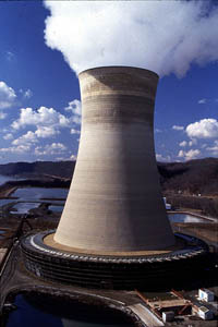
Figure 31-2. Almost all forced draft cooling towers are counterflow designs.
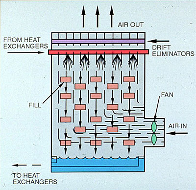
Figure 31-3. Counterflow induced draft cooling towers provide maximum heat transfer.
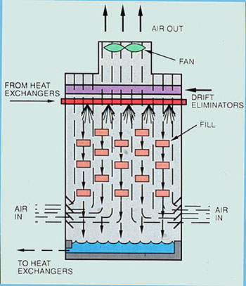
Figure 31-4. A six-cell, counterflow induced draft cooling tower. Air enters only at the bottom of the tower.
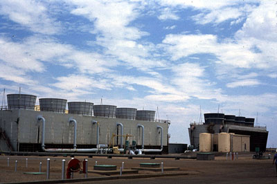
Figure 31-5. Crossflow induced draft cooling tower require less fan horsepower than the counterflow designs.
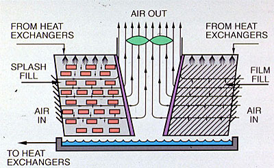
Figure 31-6. A six-cell, crossflow induced draft cooling tower.
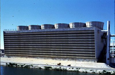
Figure 31-7. Components of a typical cooling tower. (Reprinted with permission from Power.)
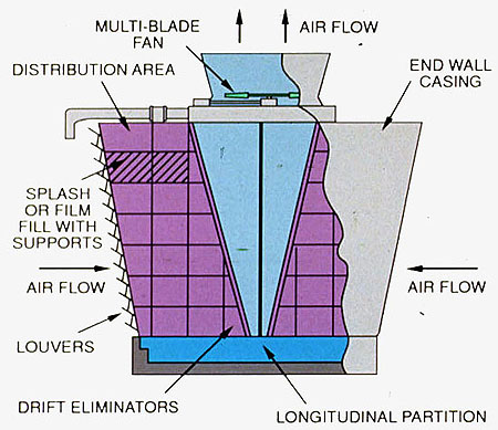
Figure 31-8. Plastic splash-type fiool can replace wood slats.
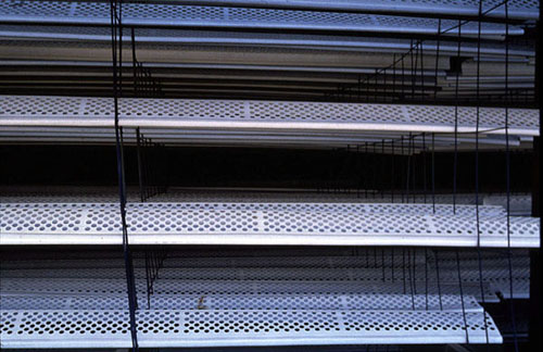
Figure 31-9. Installation of corrugated film-type tower fill can increase tower capacity relative to splash fill.
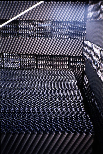
Figure 31-10. Calculation of water flows in a typical open recirculating system.
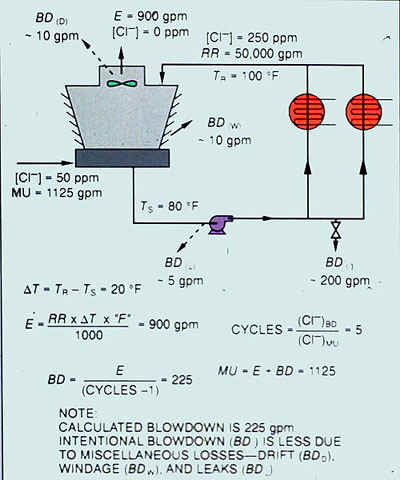
Figure 31-11. Solubility of calcium carbonate and calcum sulfate in the absence of treatment.
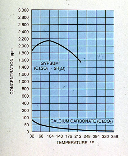
Figure 31-12. Corrosion coupon shows results of Dianodic II treatment.
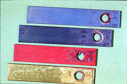
Figure 31-13. Relationship between pH and M-alkalinity shows increased buffering at higher pH.
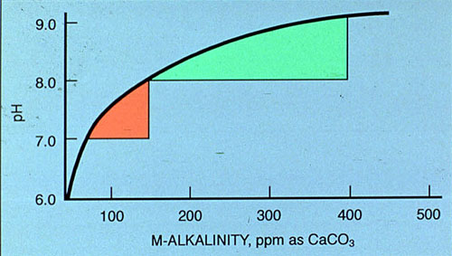
Figure 31-14. Alkaline phosphate programs provide excellent corrosion and deposition control.
Figure 31-15 & Figure 31-16
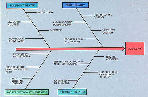
Figure 31-15. Factors influencing corrosion rate in open recirculating cooling systems.
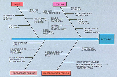
Figure 31-16. Factors contributing to deposition in open recirculating cooling systems.