CLOSED LOOP WATER SYSTEMS
A closed loop water system, also referred to as a closed recirculating water system, is a specialized setup used in various industrial applications to conserve water and minimize wastage. In a closed recirculating water system, water circulates within a closed loop, continuously moving through the system and undergoing cooling or heating processes before being reused. Closed recirculating cooling systems optimize industrial processes while reducing water consumption and environmental impacts, and play a key role in sustainable water management.
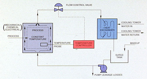
The closed recirculating cooling water system evolved from methods used for the cooling of early engine designs. In a closed water system, water circulates in a closed cycle and is subjected to alternate cooling and heating without air contact. Heat, absorbed by the water in the closed system, is normally transferred by a water-to-water exchanger to the recirculating water of an open recirculating system, from which the heat is lost to the atmosphere (Figure 32-1).
Closed recirculating cooling water systems are well suited to the cooling of gas engines and compressors. Diesel engines in stationary and locomotive services normally use radiator systems similar to the familiar automobile cooling system. Other closed recirculating cooling applications include smelt spout cooling systems on Kraft recovery boilers and lubricating oil and sample coolers in power plants. Closed systems are also widely used in air conditioning chilled water systems to transfer the refrigerant cooling to air washers, in which the air is chilled. In cold seasons, the same system can supply heat to air washers. Closed water cooling systems also provide a reliable method of industrial process temperature control.
ADVANTAGES OF CLOSED WATER SYSTEMS
Closed recirculating systems have many advantages. They provide better control of temperatures in heat-producing equipment, and their small makeup water requirements greatly simplify control of potential waterside problems. Makeup water is needed only when leakage has occurred at pump packings or when water has been drained to allow system repair. Little, if any, evaporation occurs.
Therefore, high-quality water can usually be used for makeup, and as a result, scale deposits are not a problem. The use of high-quality water also minimizes the dangers of cracked cylinders, broken heads, fouled exchangers, and other mechanical failures. Closed systems are also less susceptible to biological fouling from slime and algae deposits than open systems.
Closed systems also reduce corrosion problems drastically, because the recirculating water is not continuously saturated with oxygen, as in an open system. The only points of possible oxygen entry are at the surface of the surge tank or the hot well, the circulating pump packings, and the makeup water. With the small amount of makeup water required, adequate treatment can virtually eliminate corrosion and the accumulation of corrosion products.
LIMITATIONS OF CLOSED LOOP WATER SYSTEMS
Closed loop water systems do many advantages, but they also come with certain disadvantages that need consideration:
1. Potential for contamination: Since the same water is continuously recirculated in a closed loop, there is a risk of accumulated contaminants or impurities affecting water quality over time.
2. Risk of scaling and corrosion: Closed systems can be prone to scaling and corrosion, leading to reduced efficiency and increased maintenance requirements.
3. Limited flexibility: The design of closed loop water systems can be less flexible compared to open systems, making it challenging to adapt to changing process requirements or accommodate varying water demands.
4. Higher initial costs: Closed loop water systems often require more upfront investment due to the need for specialized equipment and controls, making their implementation costlier than traditional open systems.
5. Energy consumption: These systems may require additional energy for pumping and cooling, which can lead to increased operational costs compared to open systems that rely on natural circulation.
SCALE CONTROL
Some closed systems, such as chilled water systems, operate at relatively low temperatures and require very little makeup water. Because no concentration of dissolved solids occurs, fairly hard makeup water may be used with little danger of scale formation. However, in diesel and gas engines, the high temperature of the jacket water significantly increases its tendency to deposit scale.
Over a long period, the addition of even small amounts of hard makeup water causes a gradual buildup of scale in cylinders and cylinder heads. Where condensate is available, it is preferred for closed-system cooling water makeup. Where condensate is unavailable, zeolite softening should be applied to the makeup water.
CORROSION CONTROL
An increase in water temperature causes an increase in corrosion. In a vented system, this tendency is reduced by the decreased solubility of oxygen at higher temperatures. This is the basis of mechanical deaeration.
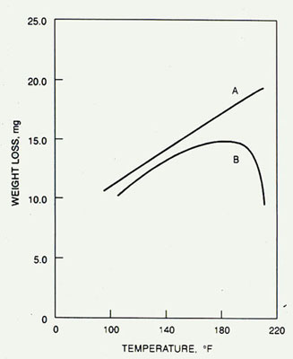
Corrosion rates at increasing water temperatures for two different sets of conditions.
Curve A plots data from a completely closed system with no provision for the venting of oxygen to atmosphere. Curve B shows data for a vented system. At up to 170°F (77°C), the curves are essentially parallel. Beyond 170°F (77°C), curve B drops off. This occurs because the lower solubility of oxygen with increasing temperatures in a freely vented system decreases the corrosion rate faster than the rise in temperature increases it. However, in many closed systems, the dissolved oxygen entering the system in the makeup water cannot be freely vented, resulting in the release of oxygen at points of high heat transfer, which may cause severe corrosion.
Untreated systems can suffer serious corrosion damage from oxygen pitting, galvanic action, and crevice attack. Closed cooling systems that are shut down periodically are subjected to water temperatures that may vary from ambient to 180°F (82°C) or higher. During shutdown, oxygen can enter the water until its saturation limit is reached. When the system is returned to high-temperature operation, oxygen solubility drops and the released oxygen attacks metal surfaces(Figure 32-1).
The metallurgy used in constructing modern engines, compressors, and cooling systems includes cast iron, steel, copper, copper alloys, and aluminum as well as solders. Nonmetallic components, such as natural or synthetic rubber, asbestos, and carbon, are also used. If bimetallic couples are present, galvanic corrosion may develop.
The three most reliable corrosion inhibitors for closed cooling water systems are chromate, molybdate, and nitrite materials. Generally, the chromate or molybdate types have proven to be superior treatments. For mixed metallurgy systems, the molybdate inhibitors provide the best corrosion protection.
Chromate closed loop water treatments
Chromate treatments in the range of 500-1000 ppm as Cr4O2¯ are satisfactory unless bimetallic influences exist. When such bimetallic couples as steel and copper are present, chromate treatment levels should be increased to exceed 2000 ppm. Maximum inhibitor effectiveness can be achieved if the pH of these systems is kept between 7.5 and 9.5.
In a closed system, it can be quite difficult to prevent corrosion of aluminum and its alloys; the pH of the water must be maintained below 9.0. Aluminum is amphoteric-it dissolves in both acid and base, and its corrosion rate accelerates at pH levels higher than 9.0. The bimetallic couple that is most difficult to cope with is that of copper and aluminum, for which chromate concentrations even higher than 5000 ppm may not be adequate.
Where circulating pumps are equipped with certain mechanical seals, such as graphite, chromate concentrations may not exceed 250 ppm. This is due to the fact that water leaking past the seals evaporates and leaves a high concentration of abrasive salts that can damage the seal.
Another problem is encountered when chromate inhibitors are used in cooling systems serving compressors that handle sour gas. If sour gas leaks from the power cylinder into the water circuit, significant chromate reduction will occur, causing poor corrosion control and deposition of reduced chromate.
In very high heat transfer rate applications, such as continuous caster mold cooling systems, chromate levels should be maintained at 100-150 ppm maximum. Under these extreme conditions, chromate can accumulate at the grain boundaries on the mold, causing enough insulation to create equipment reliability problems.
The toxicity of high-chromate concentrations may restrict their use, particularly when a system must be drained frequently. Current legislation has significantly reduced the allowable discharge limits and the reportable quantity for the spill of chromate-based products. Depending on the type of closed system and the various factors of State/Federal laws limiting the use of chromate, a nonchromate alternative may be needed.
Molybdate closed loop water treatments
Molybdate treatments provide effective corrosion protection and an environmentally acceptable alternative to chromate inhibitors. Nitrite- molybdate-azole blends inhibit corrosion in steel, copper, aluminum, and mixed-metallurgy systems. Molybdates are thermally stable and can provide excellent corrosion protection in both soft and hard water. System pH is normally controlled between 7.0 and 9.0. Recommended treatment control limits are 200-300 ppm molybdate as MoO42¯. Molybdate inhibitors should not be used with calcium levels greater than 500 ppm.
Nitrite closed loop water treatment
Nitrite is another widely accepted nonchromate closed cooling water inhibitor. Nitrite concentra-tions in the range of 600-1200 ppm as NO2- will suitably inhibit iron and steel corrosion when the pH is maintained above 7.0. Systems containing steel and copper couples require treatment levels in the 5000-7000 ppm range. If aluminum is also present, the corrosion problem is intensified, and a treatment level of 10,000 ppm may be required. In all cases, the pH of the circulating water should be maintained in the alkaline range, but below 9.0 when aluminum is present. When high nitrite levels are applied, acid feed may be required for pH control.
One drawback to nitrite treatments is the fact that nitrites are oxidized by microorganisms. This can lead to low inhibitor levels and biological fouling. The feed of nonoxidizing antimicrobial may be necessary to control nitrite reversion and biological fouling (Figure 32-3).
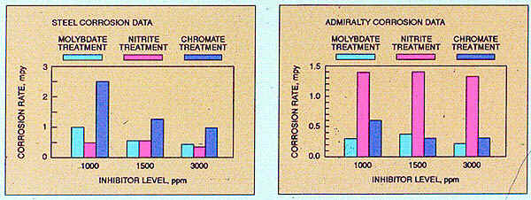
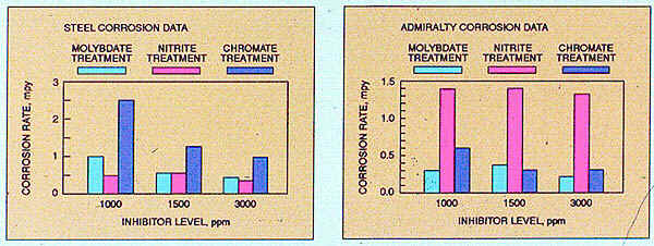
Product performance data developed in laboratory studies simulating a mixed-metallurgy closed cooling system identified steel and Admiralty corrosion rates for three closed system inhibitors at increasing treatment levels. As shown, the molybdate-based treatment provides the best overall steel and Admiralty protection. To achieve similar inhibition with chromate, higher treatment concentrations are required.
Nitrite-based treatment also provides effective steel protection, with results comparable to those obtained with molybdate; however, acceptable Admiralty corrosion inhibition is not achieved.
Closed systems often require the addition of a suitable antifreeze. Nonchromate inhibitors are compatible with typical antifreeze compounds. Chromates may be used with alcohol antifreeze, but the pH of the circulating water should be maintained above 7.0 to prevent chromate reduction. Because glycol antifreezes are not compatible with chromate-based treatments, nonchromate inhibitors should be used. Molybdate treatments should not be used with brine-type antifreezes.
In closed systems that continuously run at temperatures below 32°F (0°C), a closed brine system is often employed. The American Society of Refrigeration Engineers has established chromate limits in brine treatments. Calcium brines are limited to 1250 ppm chromate, and sodium brines are limited to 2500 ppm chromate. The pH should be 7.0-8.5 with caustic adjustment only. Some success has also been recorded with nitrite-based treatment of closed brine systems at treatment levels of about 2000 ppm as
NO2¯
Figure 32-1. Typical closed cooling system.
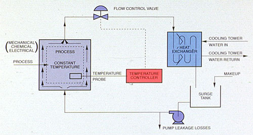
Figure 32-2. Effect of temperature on corrosion rate in closed (A) vs. open (B) systems.
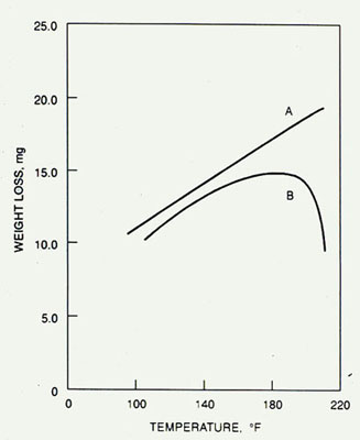
Figure 32-3. Comparison of different treatments to inhibit corrosion in a mixed-metallurgy closed system.
